
Page 837 - Industrial Power Engineering and Applications Handbook
P. 837
System voltage regulation 24/791
therefore chosen so that the receiving-end voltage is v, = E, = E$
maintained within the permissible limits under all 6
conditions of its far-end loading. Thus the receiving-end
voltage is influenced by three factors:
I
The line distributed parameters Lo and Co
The Ferranti effect due to Co and T
The p.f. of the far-end load. +-- + ___j
e12
e12
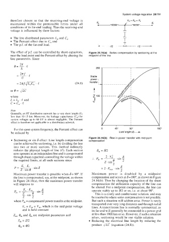
The effect of p.f. can be controlled by shunt capacitors, Figure 24.16(a) Series compensation by sectioning at the
near the load point and the Ferranti effect by altering the midpoint of the line
line parameters. Since
@=-.e
2n
a 200 -I
Stable
= 2 ~ f m e . (24.8)
where $100
L = Lo . e and
c=c,.e
Note
Generally, an HT distribution network has a very short length (e),
less than 10-15 km. Moreover, the leakage capacitance (C,,) for
system voltages up to 66 kV is almost negligible. The Ferranti
effect is therefore not applicable to a distribution network.
For the same system frequency, the Ferranti effect can 0 45" 90" 180"
be reduced by Load angle (6)-
Figure 24.16(b) Rise in power transfer with mid-point
Sectioning or sin 6 effect: Line length compensation compensation
can be achieved by sectioning, i.e. by dividing the line
into two or more sections. This method indirectly
reduces the physical length of line (e). Each section 6, = 612
now operates as an independent line and is compensated
through shunt capacitors controlling the voltage within 2. v,' . sin 6
the required limits, at all such sections since :. P, = ~
Z. sin,
L
p = E u .E . sin6 = 2 ' P,,, ' sin 6
2. sin 8
Maximum power transfer is possible when 6= 90". If Maximum power is doubled by a midpoint
the line is compensated, say, at the midpoint, as shown compensation and occurs at 6 =1 80", as shown in Figure
in Figure 24.16(a), then the maximum power transfer 24.16(b). Thus by changing the location of the shunt
will improve to compensation the utilization capacity of the line can
be altered. For a midpoint compensation, the line can
E, . E, 6 operate stably up to 612 or so, i.e. at about 90".
. sin
P, = z,.
- sin 8 This is a costly and cumbersome solution, and may
~
L L be resorted to where series compensation is not possible.
where P, = compensated power transfer at the midpoint. But such a situation will seldom arise. Power is rarely
transported over very long distances and through radial
E, = E, = V,, which is the mid point voltage lines. A transmission line is normally symmetrical, as
and is held constant its far end will generally be connected to a power grid
Z,, 0, and 6, are midpoint parameters and at less than 1000 km or so. However, if such a situation
arises, sectioning would be one viable solution.
z, = 212 Reducing the electrical line length by reducing the
e,,, = et2 product 2/Lc (equation (24.8)).