
Page 842 - Industrial Power Engineering and Applications Handbook
P. 842
24/796 Industrial Power Engineering and Applications Handbook
Line length
much longer
than ideal
Open end voltage (Set 'b' curves)
high to very high,
out of stable limits Operating
Open end voltage region
t
within permissible
\ ,t
v 1 .o
- Diminishes (referring to only E-
PO
operating region) and lines
operate underutilized.
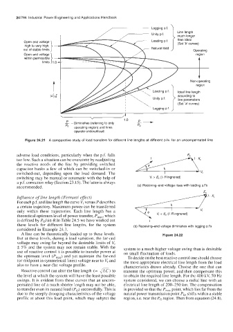
Figure 24.21 A comparative study of load transfers for different line lengths at different p.fs. for an uncompensated line
adverse load conditions, particularly when the p.f. falls
too low. Such a situation can be overcome by readjusting
the reactive needs of thc line by providing switched
capacitor banks a few of which can be switched-in or
switched-out, depending upon the load demand. The
switching may be manual or automatic with the help of V, > ES (I. R ingnored)
a p.f. corrcction relay (Section 23.15). The latter is always
recommended. (a) Receiving-end voltage rises with leading p.f's
E.
Influence of line length (Ferrunti effect)
For each p. f. and line length the curve V, versus P describes
a certain trajectory. Maximum power can be transferred
only within these trajectories. Each line length has a <I.xL V, c E, (I. R ingnored)
theoretical optimum level of power transfer, P,,,, which
is defined by Polsin 8. In Table 24.5 we have worked out I
these levels for different line lengths, for the system (b) Receiving-end voltage diminishes with lagging p.f's
considered in Example 24.1.
A line can be theoretically loaded up to these levels. Figure 24.22
But at these levels, during a load variation, the far-end
voltage may swing far beyond the desirable limits of V,
k 5% and the system may not remain stable. With the system to a much higher voltage swing than is desirable
use of reactive control it is possible to transfer power at on small fluctuation of loads.
the optimum level (PmaX) and yet maintain the far-end To decide on the best reactive control one should choose
(or midpoint in symmetrical lines) voltage near to V, and the most appropriate electrical line length from the load
also to have a near-flat voltage profile. characteristics drawn already. Choose the one that can
Reactive control can alter the line length (= m) to transmit the optimum power, and then compensate this
the level at which the system will have the least possible to obtain the required line length. For the 400 kV, 50 Hz
swings. It is evident from these curves that an uncom- system considered, we can choose a radial line with an
pensated line of a much shorter length may not be able, electrical line length of 200-250 km. The compensation
to transfer even its natural load (Po) successfully. This is is provided so that the P,,, point, which lies far from the
due to the steeply drooping characteristics of the voltage natural power transmission point Po, shifts within a stable
profile at about this load point, which may subject the region, i.e. near the Po region. Then from equation (24.8),