Page 846 - Industrial Power Engineering and Applications Handbook
P. 846

24/800  Industrial Power Engineering and Applications  Handbook   -,-  6
                        9
                  11/400 kV 4:                                  30 MVA,


                                                                       P
                 400/132 kV Jk---j                                     1
                                                                         R= 1.95 Q
                                    I
                                  Primary
                       lil transmission
                                                                       T


                  132/33 - -ev.                          capacitors          --_   B
                                                          Shunt  4
                                  -1
                                 Secondary
                                transmission
                          I
                                    I
                          I
                          I
             B         kV   A  HV   -                               +
                                                              LT loads = 29.4 MW at 0.88 p.f.
               I
                                    I
               I        I
             Section                                     (b) Details of section B-B
            B-8  under   J j      PrirJlary
           consideration   I     distribution
                           I       1                   B    O      @       O      @       O
                      -                                @ Resistance of  overhead lines of section B-B.
                   33/0.4 kV                           @ Leakage reactance of transmitter-end transformer.
                                                                                   Xc
                                                       @ Inductive reactance of overhead lines of section B-B
                                                       @)  Capacitive reactance of series capacitors.
                       Secondary
                       distribution
                        29.4  MW                          Leakage reactance of  receiving-end transformer.
               (a) Typical primary distribution network          (c) Equivalent circuit of  Section B-B
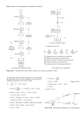
         Figure 24.25  Determining the value of series capacitors for a primary distribution  network


         To study the impact of series compensation we consider     16.62
         the full-rated current of the transformer and the line for   = 22.43 tan   2 1.43
         optimum utilization of the entire system.
                                                          = 22.43 L 17.16"              (Figure 24.26)
                   - -
              33
                 +
          E, = - I, . Z,     in kV                        :.  Voltage drop = 22.43 - 19.05
              J3
                                                          = 3.38 kV
            = 19.05 +  __
                    (1000                               or 15.07 % of E,
            = 19.05 + 0.525 x 1.95 L - 11.48" + 0.525
                                                        3      6      .      9      6      k      V
             X  13.26 L (90 - 11.48')
            = 19.0s + 1.024[cos (-11.48')  + J  sin (-1  1.48')]
              + 6.96 (cos 78.52" + J sin 78.52')
                                                                 17.16"
            = 19.05 + 1.024(0.98 - J 0.199) + 6.96(0.199 + J 0.98)
                                                                              V, = 19.05 kV   1.00 kv
            = 19.05 + 1.00 - J 0.20 + 1.38 + J  6.82            525 A
            = 2 I .43 + J 6.62                          Figure 24.26  Receiving-end voltage after shunt compensation
   841   842   843   844   845   846   847   848   849   850   851