
Page 850 - Industrial Power Engineering and Applications Handbook
P. 850
24/804 Industrial Power Engineering and Applications Handbook
is quick and matches the fast-changing load parameters
of the power network at the receiving end. They are
capable of maintaining a near-constant voltage profile
at all times at the receiving end. The correction achieved
is accurate and smooth, besides being extremely fast
and free from surges. They may be installed at strategic
locations along the line or at the receiving end. The
selection of location is an important aspect to optimize
the size of compensator and a more efficient voltage
regulation.
A fast VAr control is achieved through thyristor
switching, which by itself is capable of a stepless
variation. But switching of capacitors, which are
switched in banks, is not stepless. The SVCs may be
of the following types.
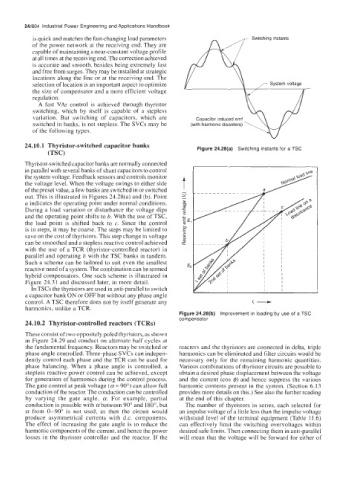
24.10.1 Thyristor-switched capacitor banks Figure 24.28(a) Switching instants for a TSC
(TSC)
Thyristor-switched capacitor banks are normally connected
in parallel with several banks of shunt capacitors to control
the system voltage. Feedback sensors and controls monitor
the voltage level. When the voltage swings to either side
of the preset value, a few banks are switched in or switched
out. This is illustrated in Figures 24.28(a) and (b). Point
a indicates the operating point under normal conditions.
During a load variation or disturbance the voltage dips
and the operating point shifts to 6. With the use of TSC,
the load point is shifted back to c. Since the control
is in steps, it may be coarse. The steps may be limited to
save on the cost of thyristors. This step change in voltage
can be smoothed and a stepless reactive control achieved
with the use of a TCR (thyristor-controlled reactor) in
parallel and operating it with the TSC banks in tandem.
Such a scheme can be tailored to suit even the smallest
reactive need of a system. The combination can be termed
hybrid compensators. One such scheme is illustrated in
Figure 24.3 1 and discussed later, in more detail.
In TSCs the thyristors are used in anti-parallel to switch
a capacitor bank ON or OFF but without any phase angle 1, -
control. A TSC therefore does not by itself generate any
harmonics, unlike a TCR.
Figure 24.28(b) Improvement in loading by use of a TSC
compensator
24.10.2 Thyristor-controlled reactors (TCRs)
These consist of two oppositely poled thyristors, as shown
in Figure 24.29 and conduct on alternate half cycles at
the fundamental frequency. Reactors may be switched or reactors and the thyristors are connected in delta, triple
phase angle controlled. Three-phase SVCs can indepen- harmonics can be eliminated and filter circuits would be
dently control each phase and the TCR can be used for necessary only for the remaining harmonic quantities.
phase balancing. When a phase angle is controlled, a Various combinations of thyristor circuits are possible to
stepless reactive power control can be achieved, except obtain a desired phase displacement between the voltage
for generation of harmonics during the control process. and the current (cos $) and hence suppress the various
The gate control at peak voltage (a = 90") can allow full harmonic contents present in the system. (Section 6.13
conduction of the reactor. The conduction can be controlled provides more details on this.) See also the further reading
by varying the gate angle, a. For example, partial at the end of this chapter.
conduction is possible with a between 90" and 1 SO", but The number of thyristors in series, each selected for
a from 0-90" is not used, as then the circuit would an impulse voltage of a little less than the impulse voltage
produce asymmetrical currents with d.c. components. withstand level of the terminal equipment (Table 11.6)
The effect of increasing the gate angle is to reduce the can effectively limit the switching overvoltages within
harmonic components of the current, and hence the power desired safe limits. Then connecting them in anti-parallel
losses in the thyristor controller and the reactor. If the will mean that the voltage will be forward for either of