Page 854 - Industrial Power Engineering and Applications Handbook
P. 854
24/808  Industrial Power Engineering and Applications Handbook
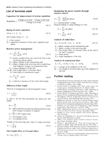
       List of formulae used                          Optimizing the power transfer through
                                                      reactive control
       Capacitors for improvement of system regulation
                                                          v,z
                                                             .
                                                      P  = -       per phase                (24.9)
                   Voltage at no load - Voltage at full load   Z,   sin e
        Regulation =
                           Voltage at no load         V,, = nominal phase voltage
                                              (24.1)   Natural loading or surge loading of  a line,
                                                              V;
       Rating of series capacitors                       Po  = - per phase                 (24.10)
                                                              zo
        kVAr = 3. If  . X,                    (24.2)                                       (24.11)
       and voltage rating = I, . X,.
        I, = line current                             Analysis of radial lines
       Xc = capacitive reactance of the series capacitors per   Es = V, cos 0, + J  Z,,  . I, . sin 8,   (24.12)
            phase
                                                       E, = phase voltage at the transmitting end.
        Reactive power management                      V, = phase voltage at the receiving end
                                                       0, = line length effect or Ferranti  effect at the end of
                                                           the line, in degrees
                                              (24.3)   I, = load current
                                                       Zo = surge impedance of the line
           P  = power transfer from one end of  the line to the
              receiving end per phase                 Analysis of symmetrical lines
             = phase voltage at the transmitting end
             = phase voltage at the receiving end, in radial lines   E, = V,,, . cos e,,, + J  Zo . I, . sin 0,   (24.1 3)
              and midpoint voltage, in symmetrical lines   V,  = voltage at the midpoint of the line
          ZO  = surge impedance of the line           0,   = line length or Ferranti effect up to the midpoint of
        sin 8  = line length effect or Ferranti effect     the line
           6 = load angle or transmission  angle
                                                      Further reading
                                              (24.4)
          X, = inductive reactance of the whole line length   I  Central Board of Power and Irrigation, India (Indian National
                                                         Committee for Cigre), Electric PoM,er Transmission at voltages
                                                         of  1000 kVatid Above, Oct. (1984).
        Influence of line length                       2  Central  Board  of  Irrigation  and  Power,  India,  Static  VAr
                                                         Compensators, Technical Report No. 41, March (1985).
        Velocity of propagation of electromagnetic waves   3  Central  Board  of  Irrigation  and  Power.  India,  Workshop  on
                                                         Series Compensation in Power Systems, Nov. (1986).
                                              (24.5)   4  Central  Board  of  Irrigation  and  Power,  India.  Workshop  on
                                                         Reactive Powercompensation Planning and Design. Dec.  ( 1993).
                                                       5  Westinghouse  Electric  Corporation,  Elecfricril Trrmsnii.ssioii
        Lo and  C,, are  the  line  parameters  per  phase  per  unit   mid Di.stri6utiori. East Pittsburgh. Pennsylvania.  USA.
        length                                         6  Engbarg. K. and Ivner. S.. Static VArSystemsfor Voltage Control
                                                         During  Steady  State  arid  Transieiit  Conditions,  May  198 I.
                                                         ReactivePowerCompensationDepartment. Sweden. May (1981 ),
          e=                                  (24.6)   7  Erinmez. LA. (ed.). Static VAr Compensators. Cigre Working
                                                         Group 38.01. Task Force No. 2 on SVC (1986).
          e= phase shift between the transmitting and receiving-   8  IEEE - Delhi Section, Advance Level Course on Reactii'e Power
              end voltages in radians or degrees         Coiitrol in Electrical  Power Systems, December (1984).
             22
          n= - or 180"respectively                     9  Kundor.  P.,  Power  SI'stem Sfability and  Corirrol, McGraw-
                                                         Hill. NewYork.
              7
          I=  line length in km                        IO  Lakervi, E. and Holmes, E.J.. Electricit?. Distributiori Nehi.orX-
                                                         Design, Peter Peregrinus, London.
          A= wavelength in km                          11  Miller.  T.J.E.,  Reactive  Power  Control  in  Electric  Sy.srems,
                                                         John Wiley, NewYork (1982).
        Voltage at the receiving end, when it is open-circuited,   12  Praaad,  J.  and  Ambarani.  V..  Static  VAr  Compensator ,for
              E                                          Industries, BHEL, India, 59th R & D Session, Feb (1994).
             cos e
        E, = I                                (24.7)   13  Research  Station.  M.P.  Electricity  Board.  Central  Board  of
                                                         Irrigation  and  Power,  India, Series  Capacitor Application  to
        Line length effect or Ferranti effect            Sitb-fraii.srinssior2  system.^ Case Studies. 'I'echnical  Keport No.
                                                         66. Nov. (1988).
                                                       I4  Weeks, W.L.. Eaii.smi,s.sion arid Distribirtioii ojElectrical Energy
        e= ?nf.JL,c,.i                        (24.8)     (DrAigri rrsprcts). Harper & Row,  New York.

