
Page 852 - Industrial Power Engineering and Applications Handbook
P. 852
24/806 Industrial Power Engineering and Applications Handbook
400 kV transmission or
132 kV distribution line
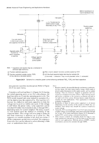
I Interrupter (
d
\
T A/ D Transformer for Reactive power
& V.T
reactive power supply.
Secondary at say, 11 kV
supply bus
Line side reactor Some fixed reactor
to limit inrush current to filter out sub-
and suppress harmonics harmonic components
and feedback
0
Note: * Capacitors and reactors may be A connected to
eliminate triple harmonics
@ Thyristor switched capacitors @) Filter circuit to absorb harmonic currents caused by TCR
@ Thyristor controlled variable reactor (TCR) @ (i)-A few fixed capacitor banks that may be normally ON.
(it may also be a saturated reactor) (it) Normally D connected. They are not grounded, when A connected
Figure 24.31 Scheme for a reactive power control showing combined TSC,, TCR, and fixed capacitors
also generate capacitive reactive power. Refer to Figure Nores
24.33 for more clarity. I Reactive control is also possible through synchronous condensers.
As they rotate, the rotor stores kinetic energy which tends to
absorb sudden fluctuations in the supply system, such as sudden
Consider a noymal load line (1) (Figure 24.32) having loadings. They are. however, sluggish in operation and very
the initial operating point at (a). On a disturbance, the expensive compared to thyristor controls. Theii rotating masses
load line shifts to (2) and the operating point to (b). The add inertia, contribute to the transient oscillations and add to
TCR would respond and some inductive reactance (X,) the fault level of the system. All these factors render them less
will be shed to raise the content of Xc. The load line will suitable for such applications. Their application is therefore
become less inductive and more capacitive to help the gradually disappearing.
voltage rise to point (c) within one cycle. If the voltage 2 Reliability of shunt or series power capacitors is of utmost
importance for the security of the system on which they are
is still below the preset value, some capacitors can be installed. Their failure may disturb the system or result in a
switched ON either electromechanically or through TSCs, system outage.
depending upon the system adopted. The delay at point 3 Generally, SVCs are designed for I1 or 33 kV and connected to
(c) will depend upon the method of switching of the a higher voltage system through a dedicated transformer through
capacitor banks. The voltage will now jump to point (d) the tertiary of the main transformer. Figure 24.33 illustrates a
and final correction is achieved up to point (e). The typical SVC system using a dedicated transformer.
sequence a-e would complete in less than two cycles if 4 Since reactive controls are normally meant for large to very
large installations, the practice so far has been to use thyristors
all the components are thyristor switched. The sequences only for such applications. With the advent of IGBTs, smaller
from a-b-c-d-e can be reduced to a-b-e allowing a little installations can now be switched through IGBTs.
over- or undershoots from c to d.