Page 847 - Industrial Power Engineering and Applications Handbook
P. 847
System voltage regulation  241801

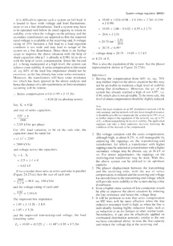
           It  is difficult to operate such a system on full load. It   =  19.05 + 1.024 (0.98 - J  0,199) + 2.761  (0.199
         is  bound  to  have  wide  voltage  and  load  fluctuations,   + J 0.98)
         more so on a line disturbance. Such a system may have
         to be operated well below its rated capacity to retain  its   =  19.05 + 1 .00 - J  0.02 + 0.55 + J  2.71
         stability. even when the voltages on the primary and the   =  20.6 + J  2.51
         secondary transformers are adjusted so that the required
         rated voltage is available at the receiving-end. A voltage   = 20.75 tan-  I  2.51
         suing of  158 between  a  full  load  to  a  load  rejection   ~  20.6
         condition  is  too  wide  and  may  lead  to  outage  of  the   =  20.75 L 6.95"
         system on a  line disturbance.  Since there is  no further
         scope  to  improve  the  above situation  with  the  help  of   :.  voltage drop = 20.75  ~  19.05 = 1.7 kV
         shunt capacitors (the p.f. is already at 0.98). let us do so   or 8.2% of E.
         with  the help of  series compensation. Since the far-end
         p.f. is being maintained at a high level, the system can   This is also the regulation of the system. See the phasor
         achieve some stability. A series compensation to the extent   representation shown in Figure  24.27(b).
         of, say  60% of  the  total  line impedance should not  be
         excessive, as the line already has some series resistance.   1njeftiuric.e.r
         Moreover,  the  transformers  will  have  some resistance   1  Raising  the  compensation  from  60% to,  say,  70%
         too  which  has  been  ignored in  the  above analysis  and   may further improve the above situation but this may
         hence the chances of a sub-synchronous or ferro-resonance   not he advisable to maintain  a high  level of  stability
         occurring will  be remote.                       during  line  disturbances.  Moreover.  the  p.f.  of  the
                                                          system has already reached a high  of  cos 6.95". i.e.
         :.  Series compensation = 0.6 (I .c)S + J  13.26)   0.99, which also is not advisable. Tu be more safe. the
                            = 8.04 R (in absolute terms)   level of shunt compensation should be slightly reduced.
         Say. x,. = 8 R
                                                          Note
         and  5ize of  series capacitors.                 Since the load variation on an HT dictriburion network  will be
                                                          only nominal. and the network will also have enough reAance.
           52s'  x 8                                      it should be possible to compensate the systeni up to 70% 01-  so.
         -                                                to further improve the regulation  of  the network.  hay  up to 5%
         -
             IO00                                         oI'E,. withom jeopardizing the level ofstnbility. Thc application
         = 3305 kVAr per phase                            engineer  can  take  a  more judiciou\  decijion.  knowing  the
                                                          condition  of the network to he compensated.
         For  10% load  variation,  to  be  on  the  safe  side.  the
         capacitors must  be rated  for:                2  The voltage variation with  the series compensation,
         = ( 1  1 )I x  220s                              although high, at about 8.2%, is still  manageable by
                                                          adjusting  the  tappings  on  the  transmitting-end
         = 3668 kVA1                                      transformer,  for  which  a  tramformer  with  higher
                                                          tappings may be selected or a transformer with a higher
         and voltage across the capacitors,               secondary  voltage may  be  chosen.  say, at  36 kV or
         v,  = I, . x,                                    so.  For  minor  adjustments,  the  tappings  on  the
                                                          receiving-end  transformer  may  be  used.  With  this,
            = 52s x  1.1  x 8                             the  above  system  can  be  utilized  to  its  optimum
            = 4.62 kV                                     capacity.
                                                        3  The  phasor  displacement  between  the  transmitting
           If we consider three units in series and nine in parallel   and  the  receiving  ends,  with  the  use  of  series
         (Figure 24.27(a)) then  the  size of each unit   compensation, is reduced and the receiving-end voltage
                                                          has moved closer to the transmitting-end voltage. which
         -- 2668  = 98.8  say.  100 kVAr                  will provide more stability to the system during a line
         -
           3x9
                                                          disturbance.
         and the  voltage rating of each unit           4  Even a higher cross-section of line conductors would
                                                          be  able to improve the  above situation by  reducing
         - 4.62 = 1.54 kV
         -
             3                                            the line resistance and hence the voltage drop.
         Thc improved line impedance                    S  It will  be pertinent to  note that  series compensation
                                                          on  HT  lines  will  be  more  effective  when  the  line
         = I.Y5+J  1326-JSO                               inductive reactance itself  is high, as when  the line is
                                                          individually feeding highly  inductive loads, such  as
         = 1.95 + J 5 26
                                                          an induction or an arc furnace or other similar loads.
         and  the  improved  transmitting-end  voltage,  the  load   Nevertheless,  it  can  also  be  effectively  applied  on
         remaining  same.                                 overloaded distribution  networks  similar to  the  one
                                                          we have considered above. to raise the line capacity
          E\=  1905+(0525L-  I148")(1.9S+JS.26)           and reduce the voltage dip at the receiving end.

