
Page 843 - Industrial Power Engineering and Applications Handbook
P. 843
System voltage regulation 24/797
= Jm
8- m1 or
Say, for an actual line length of 800 km (symmetrical), This value can be reduced by decreasing the value of X,,
which is possible by providing series capacitors in the
04,,,, dzz x 400 ( 8,o0 = midpoint Ferranti effect) line. If Xcc is the series compensation, then the modified
0~
impedance
which must be improved for, say, a 250 km radial line
i.e. 8250 - d m x 250
and hence any value of power transfer can be achieved
for 8400 to be almost equal to 8,,,, up to the theoretical P,,, (Table 24.5). But for reasons
of other parameters that may also influence the stability
d m x 400 = Jm 250 of the system, it is not practical to achieve the optimum
x
capacity utilization of the line without sacrificing the
level of stability, even when the required degree of
compensation is provided. Parameters that may influence
the stability can be one or more of the following:
1 A small value of (X, - Xcc), i.e. Xcc approaching XL,
will have more chance of a sub-synchronous resonance
(SSR) with the rotating machines and a ferro-resonance
Since a shunt compensation will reduce Xc (- Uc), it with the transformers during a switching sequence or
will not provide the desired compensation. This can be line disturbance.
achieved with the use of series compensation, C, remaining 2 Higher harmonic contents may magnify the harmonic
the same. Then currents and affect the loading capacity of the line.
3 A very close compensation, Le., a low XL - Xcc, may
also raise the fault level of the system beyond
acceptable limits.
To overcome such situations within acceptable para-
:. Compensation required = 0.61 XL0 per unit length.
Series capacitors making up 0.61 X,,. e may be introduced meters during normal operation, it has been found that
an ideal series compensation is achieved at around 40-
into the system to achieve the desired electrical line length. 70% of XL, preferably in the range of 45-60% only. The
level of compensation will depend upon the expected
Influence of surge impedance (Z,) load fluctuations and the presence of harmonic disorders
1 in the system.
Since Po - -
ZO Example 24.2
Z, p1ay.s a very significant role in the power transfer Consider the 400 kV, 50 Hz system and apply the above
capability of a line. By reducing the value of Z,, the theory. If the system has relatively fewer load fluctuations
power transfer capability of a system can be increased. and the loads are reasonably linear, then we can consider a
Since higher compensation to the extent of, say 75% of X,. Then
v,2
Po = -and
zo
and in absolute terms = d-
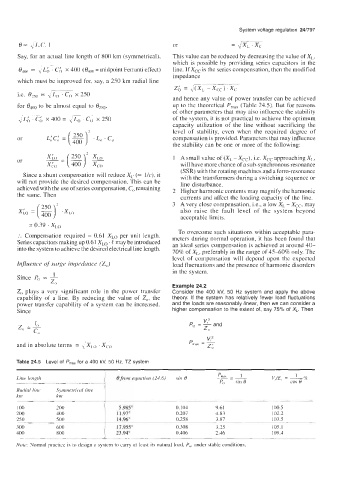
Table 24.5 Level of P,,, for a 400 kV, 50 Hz, TZ system
I pmax 1
Line length 8 from equation (24.6) sin 0 __=- sin f3 V$ES = 2%
cos e
Po
Radial line Symmetrical line
km km
100 200 5.985" 0.104 9.61 100.5
200 400 1 1.97" 0.207 4.83 102.2
250 500 14.96" 0.258 3.87 103.5
300 600 17.955" 0.308 3.25 105.1
400 800 23.94" 0.406 2.46 109.4
~~~~ ~ ~ ~
Note: Normal practice is to design a system to carry at least its natural load, Po, under stable conditions.