
Page 835 - Industrial Power Engineering and Applications Handbook
P. 835
System voltage regulation 241789
phase voltage at the receiving end in radial lines
and mid-point voltage in symmetrical lines.
(Symmetrical lines are those which are fed from
both ends such as when the far end is connected
to a power grid).
surge impedance of the line
constant for a particular line, irrespective of its
length, although L and C will rise with the line
length (L = e . L, and C = 4: . Co. if t is the length
of the line).
where Lo, C,, and R, are the line parameters, per phase
per unit length. In our subsequent analysis, we have
ignored Ro, being negligible. The standard line parameters
are normally worked out for different system networks
operative in a country by the power transmission and
Sending Length of line __c Receiving distribution authorities on the basis of conductor
end end configuration, spacing between them and the ground.
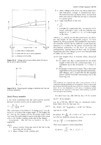
@ - V, profile without compensation
Typical data for a few voltage systems have been provided
@ - V, profile with the use of series capacitors. in Tables 24.l(a) and (b).
0- charging current profile. sin 8 = line length effect or Ferranti effect, discussed
I,,
later
Figure 24.12 Voltage and current profiles when the line at 8 = In radial lines this is determined for the entire
the far end is open-circuited
length of line while for symmetrical lines. it is
calculated up to the mid-point. i.e. it refers to
812.
t IC0 xcc 6 = load angle or transmission angle. This is the torque
angle between the receiving-end and transmitting-
end voltages, and is responsible for the required
power transfer from the transmitting end to the
receiving-end.
Note
This should not be confused with AB as used in Section 16. IO in
connection with the paralleling of two generators. There it represented
the electrical shift between the rotors of the two machines or supply
Figure 24.13 Receiving-end voltage is flattened with the use buses. If it is not eliminated, it will cause a circulating current
of series caDacitors between the two machines or the buces when running in parallel
and will add to their heating.
24.6.3 Power transfer For short lines say, 200-300 km, for a 50 IIz system
It has been established that the active power transfer sin 8 -- 8 (in radians)
through a power system can be expressed by e.g. for a 250 km, 400 kV line, as considered earlier.
from Table 24.2, for line type TZ,
(24.3) 8 = 59.85 x IO-' degree/km = 14.96' for 250 km
The expression is free from p.f. A change in p.f. (cos #), and sin 8 = 0.258
however, will adjust the torque angle, 6. The higher the
p.f. (low @), the, greater will be the torque angle 6 and In radians 8 = L?L . 8 = 1.045 x per km or 0.261
1 80
vice versa. For more details to arrive at the above derivation for 250 km (both are almost the same)
refer to the further reading at the end of the chapter.
Assumption - that the line is lossless, i.e. Ro is and 8 = E. equation (24.6)
as in
negligible. a
where Then from equation (24.8) noted later.
P = power transfer from one end of the line to the
receiving end per phase
E, = phase voltage at the sending end