
Page 828 - Industrial Power Engineering and Applications Handbook
P. 828
System voltage regulation 241783
limited use of series capacitors (Xcc) in view of a We will notice subsequently that series and rhunl
large content of I.R. See the phasor diagram in Figure compensation are complementary. What a shunt capacitor
24.5(b). Also refer to Figure 24.5(c) when R is cannot do, a series capacitor does and vice versa. On a
insignificant. Now the receiving-end voltage, V,, can secondary transmission system. say up to 66 kV, a shunt
be improved by offsetting the reactive component compensation may always be necessary to improve the
with the use of series capacitors. power factor. as the load would mainly he inductive. A
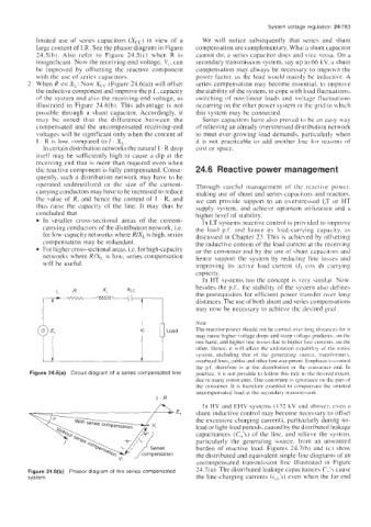
2 When R << XL: Now Xcc (Figure 24.6(a)) will offset series compensation may become essential, to improve
the inductive component and improve the p.f., capacity the stability of the system, to cope with load fluctuation\.
of the system and also the receiving-end voltage, as switching of non-linear loads and voltage fluctuations
illustrated in Figure 24.6(b). This advantage is not occurring on the other power system or the grid to which
possible through a shunt capacitor. Accordingly, it this system may be connected.
may be noted that the difference between the Series capacitors have also proved to be an easy way
compensated and the uncompensated receiving-end of relieving an already overstressed distribution network
voltages will be significant only when the content of to meet ever-growing load demands, particularly when
I . R is low. compared to I . XL2. it is not practicable to add another line for reasons of
In certain distribution networks the natural I . R drop cost or space.
itself may be sufficiently high to cause a dip at the
receiving end that is more than required even when
thc reactive component is fully compensated. Conse- 24.6 Reactive power management
quently, such a distribution network may have to be
operated underutilized or the size of the current- Through careful management of the reactive power.
carrying conductors may have to be increased to reduce making use of shunt and series capacitors and reactors.
the value of R, and hence the content of I . R, and we can provide support to an overstressed LT or HT
thus raise the capacity of the line. It may thus be supply system. and achieve optimum utilimtion and a
concluded that higher level of stability.
In smaller cross-sectional areas of the current- In LT systems reactive control is provided to improve
carrying conductors of the distribution network, i.e. the load p.f. and hence its load-carrying capacity. as
for low-capacity networks where R/XL is high, series discussed in Chapter 23. This is achieved by offsetting
compensation may be redundant. the inductive content of the load current at the receiving
For higher cross-sectional areas, Le. for high-capacity or the consumer end by the use of shunt capacitors and
networks where RIX, is low. series compensation hence support the system by reducing line losses and
will be useful. improving its active load current (I, co\ 4) carrying
capacity.
In HT systems too the concept is very similar. Now.
besides the p.f., the stability of the system also defines
the prerequisites for efficient power transfer over long
distances. The use of both shunt and series compensations
may now be necessary to achieve the desired goal.
Note
The reactive power should not be carried oker long dijtanccr for it
may cause higher voltage drops and steep \oltage gradients. on the
one hand, and higher line losses due 10 higher line currents. on the
other. Hence, it will affect the utilization capahilicy d the entiic
\y\tem, including that of the generating source, tran\former\.
overhead lines, cables and other line equipment. Emphasis to control
the p.f. therefore is at the distribution or the conbumcr end. In
Figure 24.6(a) Circuit diagram of a series compensated line practice. it is not possible to follow this rule to the desired extent.
due to many constraints. One constraint is ignorance on thr part of
the consumer. It is therefore essential to cornpenhate the omitted
uncompensated load at the secondary tran\mi\sion.
I, . R
/w In HV and EHV systems (132 kV and above), even a
shunt inductive control may become necessary to offset
the excessive charging currents, particularly during no-
load or light-load periods, caused by the distributed leakage
capacitances (C<>’s) of the line, and relieve the systcm.
particularly the generating source. from an unwanted
burden of reactive load. Figures 24.7(h) and (c) show
the distributed and equivalent single-line diagrams of an
uncompensated transmission linc illustrated in Figure
Figure 24.6(b) Phasor diagram of the series compensated 24.7(a). The distributed leakage capacitances C,,’s cause
system the line-charging currents (ice's) even when the far end