Page 820 - Industrial Power Engineering and Applications Handbook
P. 820
Power caoacitors: behaviour, switching  and improvement of power factor 23/775
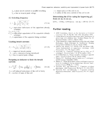
             I,,,  = peak inrush current in parallel  switching   r = mean radius of the coil in cm
             V,  = line to neutral  peak voltage         rl = radius of the cross-section of  the coil  in cm
                                                        Determining the kVAr rating for improving p.f.
          (ii) Switching frequency                      from cos 4, to cos 42

                                                         kVAr,  - kVAr2 = kW(tan q5,  - tan  &) = kW.K  (23.17)
                                               (23.14)
           L,,  = equivalent  inductance  of  the  capacitors already
               switched                                  Further reading
          LZeq = L,,  + L,
          C,,,  = equivalent capacitance of the capacitors already   I  AIEE  Committee.  Report  017  the  Operation  of  Switched
               5 witched                                   Cupucirors, Vol. 74, Part Ill,  1255-1261.  December (1955).
           C,  = capacitance of the capacitor being switched   2  Central Board of  Irrigation  and Power, 1ndia;Interference  of
                                                           power  lines  with  telephone  lines’ Technml Report  No.  29.
                                                           Research Scheme on Power, March (1982).
          Limiting inrush currents                       3  ‘Cigre, Harmonics voltage unbalanced voltage dips and voltage
                                                           fluctuations’. Study  Committee  36,  ’Interference,’  Working
                       c, ’ c,                             Group 36.05, Published by  Electra,  March (1989).
                                               (23.15)   4  Johnson, LB., Schultz, A.J., Schultr. N.R.  and Shores. R.B..
                                                           ’Some  fundamentals  on  capacitance  switching‘.  AIEE
                                                           Trunsuctions. 727-736,  August (1955).
          I,:,  = improved inrush current                5  Narasimha,  G., ‘Capacitor  switching  and  its  effect  on  LT
           L = series inductance being introduced          switchgear’, Electrical  India, 5-8,  30 November (1982).
           V,,  = line to neutral  peak  voltage         6  Savir-Silbermann, S., ‘Surges caused by  switching of capacitor
                                                           banks’, Electrical  Energ?;  88-95.  March (1958).
                                                         7  Sharma. S.P., ‘Switching capacitor banks in L.T. switchgear’,
          Designing an inductor to limit the inrush        IEEMA Journal, September (1989).
          currents                                       8  Shenoy, G., ‘Reducing harmonic currents and improving powel-
                                                           factor  in  installations  having  predominant  thyristor  loads’,
                                                           Siemens  Circuit, XVII, No.  1  (1982).
                                                         9  Vansickle,  R.C.  and  Zaborszky.  J.,  ’Capacitor  switching
                                                           phenomena’. AI€€  Trun.saction.s, 70, Part I,  151-159  (195 I).
                                                         IO  Vansickle,  R.C.  and  Zaborszky,  J.,  ‘Capacitor  switching
          L = self-induced inductance of the coil in henry   phenomena with resistors’. AIEE Trmscrcrion.~. 97 1-977. August
          N  = number of turns of  the coil                (1954).

