
Page 816 - Industrial Power Engineering and Applications Handbook
P. 816
Power capacitors: behaviour, switching and improvement of power factor 23/771
-9
PF
..
r set i On
IJ
Supply
2
Operate
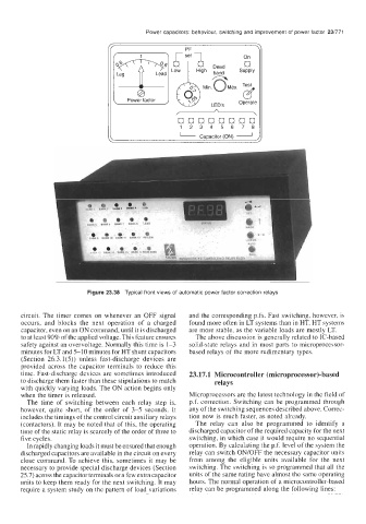
Figure 23.38 Typical front views of automatic power factor correction relays
circuit. The timer comes on whenever an OFF signal and the corresponding p.fs. Fast switching, however, is
occurs, and blocks the next operation of a charged found more often in LT systems than in HT. HT systems
capacitor, even on an ON command, until it is discharged are more stable, as the variable loads are mostly LT.
to at least 90% of the applied voltage. This feature ensures The above discussion is generally related to IC-based
safety against an overvoltage. Normally this time is 1-3 solid-state relays and in most parts to microprocessor-
minutes for LT and 5-10 minutes for HT shunt capacitors based relays of the more rudimentary types.
(Section 26.3.1(5)) unless fast-discharge devices are
provided across the capacitor terminals to reduce this
time. Fast-discharge devices are sometimes introduced 23.17.1 Microcontroller (microprocessor)-based
to discharge them faster than these stipulations to match relays
with quickly varying loads. The ON action begins only
when the timer is released. Microprocessors are the latest technology in the field of
The time of switching between each relay step is, p.f. correction. Switching can be programmed through
however, quite short, of the order of 3-5 seconds. It any of the switching sequences described above. Correc-
includes the timings of the control circuit auxiliary relays tion now is much faster, as noted already.
(contactors). It may be noted that of this, the operating The relay can also be programmed to identify a
time of the static relay is scarcely of the order of three to discharged capacitor of the required capacity for the next
five cycles. switching, in which case it would require no sequential
In rapidly changing loads it must be ensured that enough operation. By calculating the p.f. level of the system the
discharged capacitors are available in the circuit on every relay can switch ON/OFF the necessary capacitor units
close command. To achieve this, sometimes it may be from among the eligible units available for the next
necessary to provide special discharge devices (Section switching. The switching is so programmed that all the
25.7) across the capacitor terminals or a few extra capacitor units of the same rating have almost the same operating
units to keep them ready for the next switching. It may hours. The normal operation of a microcontroller-based
require a system study on the pattern of load variations relay can be programmed along the following lines: