
Page 807 - Industrial Power Engineering and Applications Handbook
P. 807
Power capacitors: behaviour, switching and improvement of power factor 231763
capacitor kVAr may exceed the motor reactive component, I I
and cause a leading power factor. A leading p.f. can
produce dangerous overvoltages. This phenomenon is lIC IIC
alco true in an alternator. Transformer - 1 transformer - 2
If such a situation arises with a motor or an alternator,
it is possible that it may cause excessive torques. Keeping
these parameters in mind, motor manufacturers have
recommended compensation of only 90% of the no-load
kVAr of the motor. irrespective of the motor loading.
This. for all practical purposes and at all loads, will
improve the p.f. of the motor to around 0.9-0.95. which
is satisfactory.
Table 23.7, based on the recommendations of motor
manufacturers. suggests the likely capacitor ratings for
different motor ratings and speeds. For higher ratings. - 1 Power Control
interpolate or calculate the rating as illustrated in Section Outgoing feeders Centre (PCC)
33.12.2. -- --- -- -
I
Motor Control Distribution
Centre (MCC) Board (DB)
for utilities I
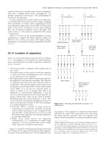
23.1 4 Location of capacitors
Refer to a typical distribution network shown in Figure
13.3 1. The capacitor is of maximum use when located as
near to the load-point as possible, especially in induction
motors. because:
The reactive load is confined to the smallest part of
the system.
The motor starter can be used to switch thc capacitor
ax well as the motor, eliminating the cost of an extra
\witch and fuse for the capacitor.
By employing the same switch for motor and capacitor,
the capacitor is automatically controlled. Thc capacitor Motor feeders
is required to be in the circuit only when the motor is MCB Distribution I
in operation. The capacitor panel can be a part of the Board (DB) for
main power control centre (PCC) or the motor control
centre (MCC) or il can also be a separate pancl, as
shown in Figure 23.32. In group loads such as an
industrial or a power-house application, it may he
more economical and practical to install capacitors in
groups, whose kVAr value can be varied as desired.
depending upon the system loading at a time. This
can also he done automatically through a preset power
factor correction relay (Figure 23.38). The advantages
of a group installation can be: Figure 23.31 Receiving and distribution of power in an
industrial unit
Diversity: When a number of motor loads are
connected on a common bus. normally not all the
motors will be operating at a time. A capacitor bank in position I” the capacitor is connected on the motor
near the MCC would permit the use of lcsscr total side after the starter. The same starter will switch both
kVAr than if the capacitors were located separately the motor and the capacitor. Since the capacitor will
at each individual load. reduce the kVAr demand, the current through the starter
When many small motors are operating
simultaneously it is cconomical to install larger
capacitors in several sections than to have many *‘When adopting this location. care must he taken that the capacitor\
small capacitors installed at each motor. are not wbjected to a quick reclosing (Section 2.5.6.2(1)). In a
y/A or A/T switching the capacitors would be subjected to a qulck
reclosing and may endanger the motor inwlation as well as it\
Figure 23.33 and 23.34 illustrate the locations discussed own. In this ca\e it would be e\sentinl to make a wtable modification
so far. Figure 23.33 suggests the locations of the capacitor in its switching circuit to keep the capacitor out of the circuit
in respect of the motor whose p.f. is to be improved, e.g. during thc changeover, as suggested in Figure 25.7.