Page 793 - Industrial Power Engineering and Applications Handbook
P. 793

Power capacitors: behaviour, switching and improvement of power factor  231749

                                                                        352
                                                       Actual, p.f.,  cos  $2  =  -
                                                                        525
               132133 kV
                                                                      = 0.67
                                                       ..           $2  = 47.9"
              R = 1.95Q
                                                       Let us improve the apparent  load p.f. to 0.98
                                                       i.e. cos q3 = 0.98
                                                       and   $3 = 11.48'
                                                       From Example 24.3 and Figure 24.25(b) inductive reactance
                                                       of  line = 6 Q per phase.
                    - suppress 5th harmonic            Reactance of each transformer  = 3.63 (2.
                       quantities
                       I L I I I 117
             4                                         Total inductive reactance of the network = 13.26 (1 per phase
                                                       :.                13.26
                                                                          27c  f
                                                           line inductance  L  =  ~
                                                                        = 42.23 mH/phase
                                                       Since the p.f. is to be improved from 0.88 to 0.98
                                                       :.  Shunt  reactive compensation required
                                                       Ixc = 400 [sin 9, - sin  $3]
                                                          = 400 [sin 28.36 - sin 11.481
            1111111 h,
            TTTTTTTl                                      = 400 [0.475 - 0.1991
                                                          = 110.4 A

                                                       and kVAr required  = & x 33 x 11 0.4
                                                                    = 6310 kVAr
                                                                   Say, 6300 kVAr
                                                       The shunt  capacitors  can be provided on the  LT or the  HT
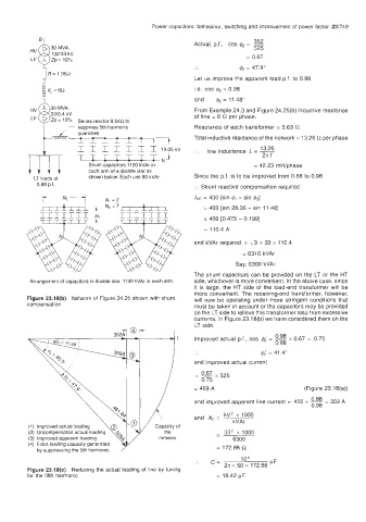
         Arrangement of capacitors in double star, 11 20 kVAr in each arm.   side, whichever is more convenient. In the above case, since
                                                       it  is large, the  HT side of  the  load-end transformer  will  be
                                                       more convenient. The  receiving-end transformer, however,
        Figure 23.18(b)  Network of  Figure 24.25 shown with shunt   will  now be operating under  more stringent  conditions that
        compensation                                   must be taken in account or the capacitors may be provided
                                                       on the LT side to relieve this transformer also from excessive
                                                       currents. In Figure 23.18(b) we have considered them on the
                                                       LT side.
                                                                              0.98
                                                       Improved actual p.f., cos   =  ~   x 0.67 = 0.75
                                                                              0.88
                                                                          4; = 41.4"
                                                       and improved actual current
                                                       -- 0.67 x 525
                                                       -
                                                         0.75
                                                       = 469 A                        (Figure 23.18(a))
                                                       and improved apparent  line current =  400 x 0.88 = 359 A
                                                                                       0.98
                                                               kV'  x  1000
                                                       and  X,  =
                                                                  kVAr
                                                             -  33'  x 1000
                                                                  6300
                                                             = 172.86 R
                                                       :.   c=      106     KF
        Figure 23.18(c) Reducing the actual loading of  line by tuning   27c  x 50 x  172.86
        for the fifth  harmonic                              = 18.42 pF
   788   789   790   791   792   793   794   795   796   797   798