
Page 790 - Industrial Power Engineering and Applications Handbook
P. 790
23/746 Industrial Power Engineering and Applications Handbook
HT, 132 kV (typical)
This provision will also account for any diminishing 132/11 kV
variation in C, as may be caused by ambient temperature,
production tolerances or failure of a few capacitor elements
or even of a few units during operation.
The p.f. correction system would thus become inductive
for most of the current harmonics produced by power
electronic circuits and would not magnify the harmonic
effects or cause disturbance to a communication system
if existing in the vicinity (see Figure 23.14). A filter
circuit can be tuned to the lowest (say the fifth) harmonic
produced by an electronic circuit. This is because LT
capacitors are normally connected in delta and hence do
not allow the third harmonic to enter the circuit while the
HT capacitors are connected in star, but their neutral is
left floating and hence it does not allow the third harmonic
to enter the circuit. In non-linear or unbalanced loads,
however, the third harmonic may still exist. For a closer
compensation, uni-frequency filters can be used to
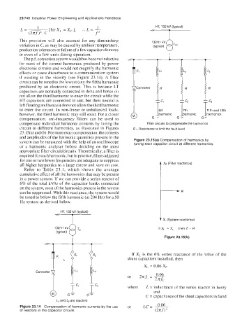
compensate individual harmonic contents by tuning the Filter circuits to compensate the harmonics
circuit to different harmonics, as illustrated in Figures R = Resistance to limit the fault level
23.15(a) and@). For moreexact compensation, thecontents
and amplitudes of the harmonic quantities present in the
system can be measured with the help of an oscilloscope Figure 23.1 5(a) Compensation of harmonics by
tuning each capacitor circuit at different harmonics
or a harmonic analyser before deciding on the most
appropriate filter circuit/circuits. Theoretically, a filter is
required for each harmonic, but in practice, filters adjusted
for one or two lower frequencies are adequate to suppress
all higher harmonics to a large extent and save on cost. t X, (Filter reactance)
Refer to Table 23.1, which shows the average
cumulative effect of all the harmonics that may be present
in a power system. If we can provide a series reactor of
6% of the total kVAr of the capacitor banks connected
on the system, most of the harmonics present in the system
can be suppressed. With this reactance, the system would -R
be tuned to below the fifth harmonic (at 204 Hz) for a 50
Hz system as derived below.
,!:,HT, 132r (typical) t X, (System reactance)
T~,
132/11 kV Q If X, = X, then Z= R
(typical) Figure 23.15(b)
If X, is the 6% series reactance of the value of the
shunt capacitors installed, then
XL = 0.06 Xc
0.06
or 2nfL = -
2 xfc
& .Ic1 fc2 where L = inductance of the series reactor in henry
and
G-
C = capacitance of the shunt capacitors in farad
L, and L, are reactors
0.06
Figure 23.14 Compensation of harmonic currents by the use or LC= -
of reactors in the capacitor circuits (2nf)’