
Page 870 - Industrial Power Engineering and Applications Handbook
P. 870
25/822 Industrial Power Engineering and Applications Handbook
Power supply
R Y B N -
CF
T T T 1 1 T -Y
M
tD I
1
'1 h3
-N
ff
delay trip
Y
Power circuit
Control circuit
M - Main contactor h,, b, h3 - Indicating lights
D - Delta contactor TD.0. - Time delay open contact
S - Star contactor OCR - Over current relay
C - Capacitor contactor T - Timer
I I
Motor-stator
winding
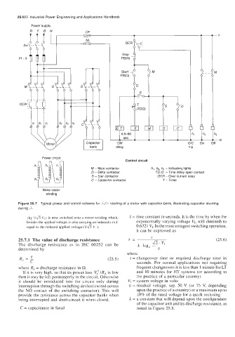
Figure 25.7 Typical power and control scheme for ,k/P starting of a motor with capacitor bank, illustrating capacitor shorting
during
(by I/& V,) is now switched onto a motor winding which, z = time constant in seconds. It is the time by when the
besides the applied voltage, is also carrying an induced e.m.f. exponentially varying voltage VI, will diminish to
equal to the reduced applied voltage (I/& V, ). 0.6321 V,. In the most stringent switching operation,
it can be expressed as
25.7.1 The value of discharge resistance (25.6)
The discharge resistance as in IEC 60252 can be
determined by
R, = 5 (25.5) where
t = changeover time or required discharge time in
seconds. For normal applications not requiring
where R, = discharge resistance in R. frequent changeovers it is less than 1 minute for LT
If it is very high, so that its power loss V,' lRd is low and 10 minutes for HT systems (or according to
then it may be left permanently in the circuit. Otherwise the practice of a particular country)
it should be introduced into the circuit only during V, = system voltage in volts
interruption through the switching device) (wired across u = residual voltage, say, 50 V (or 75 V, depending
the NO contact of the switching contactor). This will upon the practice of a country) or a maximum up to
provide the resistance across the capacitor banks when 10% of the rated voltage for a quick reclosing
being interrupted and short-circuit it when closed. k = a constant that will depend upon the configuration
of the capacitor unit and its discharge resistance, as
C = capacitance in farad noted in Figure 25.8.