Page 871 - Industrial Power Engineering and Applications Handbook
P. 871

Making capacitor units and ratings of  switching devices  25/823
         a                                                   -  log,  14.67
                                                                  30

                                                             -
                                                                     or  11.17seconds
                                                             -- 30
                                                               2.686
                                                       and discharge resistance
                1
              k=
                                                        R,  =   11'17   (2  = 93 k12, say, 100 kC2
                                                            120 x  10-6
                                          R            If the closing period is only 15 seconds, the required discharge
                                        k= 113
                                                       resistance will become 50 kR. The resistance loss in 100 kQ,
                                                       discharge resistance
                                                         v,"
                                                        --   i.e.   4152   or  1.72 watts
                                                         Rd      100 x  103
                                                       and 3.44 watts  in a 50 kQ discharge  resistance.  Since the
                                                       loss  is  negligible the  resistance may  be left  in the  circuit
                                                       permanently.
                                                       25.7.2  The value of a series inductor
                                                       In  an  L  and  R  dampening  circuit  the  capacitor  will
                             k= 1                      discharge according to the following:

                                                                                             (25.7)


                                                                       L      VP
                                                       i.e.      t = 2 x - log,  - seconds   (25.8)
                                                                       R
                                                                         .
                                                                               U
                 k- 1                  k=3             where
                                                         t =changeover  time  or  required  discharge  time  in
                                                            seconds
                                                         L = series inductance in the circuit in henry
                                                        R = series resistance in the circuit in Q.
                                                            ziz
                                                        vp = -.  v,  = 1  P.U.
                                                            43
                                                         u = residual voltage, say, 50 V or 75 V  as noted earlier,
                                                            a maximum up to  10% of  the rated  voltage for a
                                                            quick reclosing.
                    R                                  Example 25.5
                   k= 1                  k=3           Determine the discharge device for the discharge of a three-
                                                       phase 6.6 kV, 50 Hz, 1000 kVAr, y-connected capacitor bank,
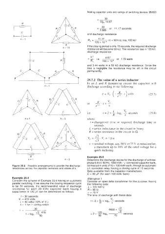
         Figure 25.8  Possible arrangements to provide the discharge   connected in units of 10 x 100 kVAr each, through an automatic
         resistances across the capacitor terminals and values of  k   p.f. correction relay, having a closing cycle of  10 seconds.
                                                       Data available from the capacitor  manufacturer,
                                                       C = 30 pF (for each 100 kVAr bank)
         Example 25.4                                  Alternative  1
         Consider the scheme of Example 23 4 having an automatic   Consider an open delta transformer for this purpose, having
         parallel switching  If  we assume the closing sequence cycle   the following data:
         to  be  30  seconds,  the  recommended value  of  discharge   L = 120 henry
         resistance  for  each  20  kVAr  capacitor  bank  having  a   R=90Q
         capacitance of  120 pF can be determined as follows   u=75v
                                                       The time of discharge with these data
              t = 30 seconds
             VI  = 415 volts                                   L      VIJ
              u = 40 volts (10% Of  V,)                   t = 2 x  - x log,  - seconds
                                                               R
                                                                       U
              k  = 1 for D configuration
                       30                                            6600 x   45
         '.   z=                                                          ~
                                                              120
                                                                 log,
                 1 x  log,   fi 415                      = 2 x  -             seconds
                          40                                  90        75
   866   867   868   869   870   871   872   873   874   875   876