
Page 976 - Industrial Power Engineering and Applications Handbook
P. 976
@
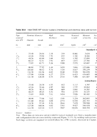
Table 30.8 lndal D50S WP tubular busbars (mechanical and electrical data and current rating)
Wull Anw Nominal Moment Section Radiw of G M Ll
thickne.s.s weigh/ of inertirr modulus gyrotiorz OS
InJide
in. tnm nini mm mm- c 111
~~ ~
(standard iron pipe sizes)
1 33.40 26 64 3.38 319 0.861 3.634 0.857 1.068 I560 98 1 186.7 675 815
I ‘I4 42.16 35 04 3.56 432 1.166 8. 104 3.844 1.371 1991 72 7 171.3 845 1010
1 (II 48.26 40 90 3.68 515 1.392 12.899 5.345 1.581 2 291 60 7 162.7 960 1160
2 60.33 52 51 3.91 693 1.871 27.709 9.186 1.999 2 878 45 1 148.3 1245 1440
2‘12 73.03 62 71 5.16 I 100 2.970 63.683 17.45 I 2.406 1 475 28 4 136.2 1720 1950
~ ~~~
~~ ~~
3 88.90 77 92 5.49 1439 3.884 125.606 28.258 2.957 4.267 21 8 123.7 2130 2350
3 I/? 101.60 90 12 5.74 1729 4.667 199.279 39.227 3.396 4.877 17 4 115.2 2510 2750
4 114.30 102 26 6.02 2048 5.529 301.039 52.675 3.835 5.514 15 3 107.6 2800 3050
4‘12 127.00 114 46 6.27 2379 6.423 434.683 68.454 4.275 6.160 I3 2 100.1 3160 3420
5 141.30 128 20 6.55 2724 7.490 63 1.007 89.326 4.770 6.853 11 3 93.8 3550 3810
(extra-heavy iron pipe sizes)
1 33.40 24 30 4.55 412 1.113 4.395 2.632 1.033 1.52 I 76 0 188.3 745 925
I ‘I4 42.16 32 46 4.85 568 1.535 10.064 4.774 1.330 1.95 1 55 1 172.6 975 I I70
1 ‘I? 48.26 18 10 5.08 689 1.861 16.283 6.748 1.537 2.245 45 4 164.0 I125 1335
2 60.33 49 25 5.54 954 2.575 36.125 1 1.977 1.947 2.835 32 9 149.3 1465 I680
2112 73.03 59 01 7.01 1454 3.926 80.183 2 1.954 2.347 3.414 21 5 137.1 1955 2230
~ ~~
~~~ ~ ~~~ ~
3 88.90 71 66 7.62 I946 5.254 162.093 36.466 2.885 4. I78 16 1 124.7 2470 2700
3 Ill 101.60 85 44 8.08 2374 6.410 26 1.393 5 1.4.55 3.320 4.801 I3 2 116.1 2x50 3160
4 114.30 97 18 8.56 2844 7.678 199.998 69.989 3.752 5.43 I II 0 108.3 3260 3590
411: 127.00 I OX 96 9.02 3343 9.027 584.938 92. I 15 4. I83 6.045 94 100.7 3700 4040
5 141.30 122 24 0.53 3947 10.656 860.350 I2 1.772 4.67 I 6.746 8 0 94.5 4 I90 4550
~~~~~~~
So LII-CP: I nd al co
Note Thcsc data are indicative and provided for typical standard \i/rs from a manufacturer. Busbar\ larger than the ahovc arc gcncrally not manufiictui-ed in tuhula~- sections hut 111 \cction\
and configurations that are convenient by extrusion (Figure 31. 15). By welding such sections. nnc can form any desired hire of tubular or any other conductor shape (hexagonal or octagonal).
Such largc wctions are required for isolated phase bu\ (IPB) system\, discussed in Chapter 31.