
Page 305 - Industrial Process Plant Construction Estimating and Man Hour Analysis
P. 305
286 Appendix F
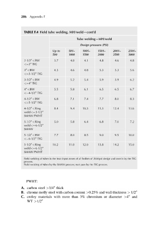
TABLE F.4 Field tube welding, MH/weld—cont’d
Tube welding—MH/weld
Design pressure (PSI)
Up to 501– 1001– 1501– 2001– 2501–
500 1000 1500 2000 2500 3000
2-1/2 <BW 3.7 4.0 4.1 4.8 4.6 4.8
00
00
<¼3 TIG
00
3 <BW 4.3 4.6 4.8 5.3 5.3 5.6
<¼3-1/2 TIG
00
00
3-1/2 <BW 4.9 5.2 5.4 5.9 5.9 6.2
<¼4 TIG
00
4 <BW 5.5 5.8 6.1 6.5 6.5 6.7
00
<¼4-1/2 TIG
00
4-1/2 <BW 6.8 7.1 7.4 7.7 8.0 8.3
00
<¼5-1/2 TIG
00
4-1/2 <Ring 8.4 9.4 10.3 11.5 12.4 13.6
00
weld<¼5-1/2 00
SMAW PWHT
5-1/2 <Ring 5.0 5.8 6.4 6.8 7.0 7.2
00
weld<¼6-1/2 00
SMAW
5-1/2 <BW 7.7 8.0 8.5 9.0 9.5 10.0
00
<¼6-1/2 TIG
00
5-1/2 <Ring 10.2 11.0 12.0 13.8 14.2 15.0
00
weld<¼6-1/2 00
SMAW PWHT
Field welding of tubes in the heat input zones of all boilers of 2000psi design and over is by the TIG
process.
Field welding of tubes by the SMAW process; root pass by the TIG process.
PWHT:
00
A. carbon steel >3/4 thick
B. chrome molly steel with carbon content >0.25% and wall thickness > 1/2 00
00
C. croloy materials with more than 3% chromium or diameter >4 and
WT >1/2 00