
Page 92 - Industrial Ventilation Design Guidebook
P. 92
4.! FLUID FLOW 57
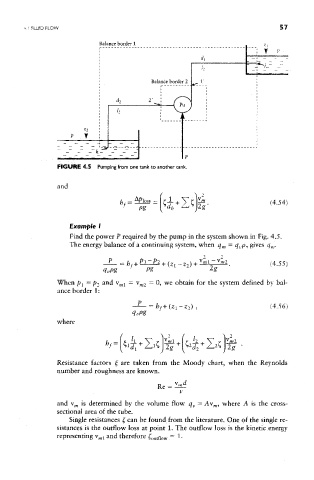
FIGURE 4.5 Pumping from one tank to another tank.
Example I
Find the power P required by the pump in the system shown in Fig. 4.5.
The energy balance of a continuing system, when q m = q up, gives q m.
When p^ — p2 and v ml = v w2 — 0> we obtain for the system defined by bal-
ance border 1:
where
Resistance factors £ are taken from the Moody chart, when the Reynolds
number and roughness are known.
and v m is determined by the volume flow q v = Av OT, where A is the cross-
sectional area of the tube.
Single resistances £ can be found from the literature. One of the single re-
sistances is the outflow loss at point 1. The outflow loss is the kinetic energy
representing v ml and therefore £ outflow = 1.