Page 96 - Industrial Ventilation Design Guidebook
P. 96

4,1 FLUID FLOW                                                            61


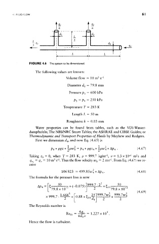
                  FIGURE 4.6 The system to be dimensioned.

                     The following values are known:
                                                         3
                                       Volume flow = 10 m  s" 1
                                       Diameter d 0 = 79.8 mm
                                        Pressure p () = 600 kPa

                                           p2=p4 = 250 kPa

                                     Temperature T = 283 K
                                          Length L = 50 m

                                       Roughness k — 0.03 mm
                     Water properties can be found from tables, such as the VDI-Wasser-
                  dampftafeln; The NBS/NRC Steam Tables; the ASHRAE and CIBSE Guides; or
                  Thermodynamic and Transport Properties of Fluids by Mayhew and Rodgers.
                     First we dimension c/ 4, and now Eq. (4.65} is


                                                                               2
                                                              3
                 Taking z 0 = 0, when T = 283 K, p = 999.7 kg/rrr , v = 1.3 x 1(H m s and
                           =
                                                                 1
                      =
                  tfv<  <?!/  10  m3 s ~*' Thus the flow velocity WQ = 2 ms" . From Eq. (4.67) we re-
                 ceive
                 The formula for the pressure loss is now


                 The Reynolds number is


                 Hence the flow is turbulent.
   91   92   93   94   95   96   97   98   99   100   101