
Page 200 - Industrial Wastewater Treatment, Recycling and Reuse
P. 200
174 Industrial Wastewater Treatment, Recycling, and Reuse
immobilized or supported catalyst reactors are preferred, but slurry reactors
can also be used if better separation characteristics or lower loading of photo-
catalysts is achieved. Most of the relevant studies have been done using ultra-
sound as a means of generating cavitation coupled with photocatalytic
oxidation, whereas only few studies are available where HC has been used
in combination with the photocatalysis (Wang et al., 2011b). In the case of
HC, simultaneous processing is difficult to achieve because of complexity
in designing and fabricating a hydrodynamically cavitating device mounted
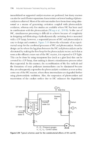
with a UV lamp; however, a sequential process of HC and photocatalyst is
easy to design and construct. Figure 3.10 shows the schematic of an experi-
mental setup for the combined processes of HC and photocatalyst. Another
design can be where the lag phase between the HC and photocatalysis can be
eliminated by making the flow loop for the photocatalytic rector, such that as
soon as the effluent comes out of the HC reactor, it is exposed to UV light.
This can be done by using transparent line (such as a glass line) that can be
covered by a UV lamp, thus making it almost a simultaneous process rather
than sequential. In this manner, the recombination of the free radicals and
the formation of toxic pollutant intermediates can be eliminated because
they are subsequently exposed to the photocatalytic oxidation as soon as they
come out of the HC reactor, where these intermediates are degraded further
using photocatalytic oxidation. Also, the suspension of photocatalyst and
reactivation of the catalyst surface due to HC enhances the degradation
P 2
Main line
Bypass
line
UV assembly Cooling Venturi
water out
UV tube
P 1
Cooling Tank V 2 V 3
water in
V 1
Pump
P , P - Pressure gauges
1
2
, V , V - Control valves
V 1 2 3
Figure 3.10 Typical schemes used for the combinatorial effects of UV and HC.