
Page 257 - Industrial Wastewater Treatment, Recycling and Reuse
P. 257
Novel Technologies for the Elimination of Pollutants 231
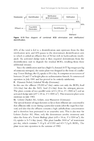
Nitrification
Wastewater Denitrification Nitrification
BOD elimination
40%
60%
Final BOD
Effluent Denitrification
Elimination
Methanol
Figure 5.13 Flow diagram of combined BOD elimination and nitrification/
denitrification.
40% of the total is fed to a denitrification unit upstream from the first
nitrification unit, and 60% passes to the downstream denitrification unit
to which is added an effluent free of N but rich in hydrocarbons (meth-
anol). An activated sludge tank is then required downstream from the
denitrification unit to degrade the residual BOD 5 resulting from these
additional streams.
Since the nitrification unit has a high O 2 demand (4.57 kg oxygen per kg
of ammonia nitrogen), the entire plant was designed in the form of a multi-
step Tower Biology; the O 2 uptake is 50 t/day. It comprises seven towers of
between 24 and 17 m height plus six sedimentation funnels. It commenced
operation in July 1981 and has proved to be entirely satisfactory.
F. Dynamit Nobel, Lulsdorf Works (Germany)
3
In this case the effluent (15,000 m /day) carries not only the BOD 5 load
(14 t/day) but also the NO 3 load (3 t/day) from the nitrogen process.
3
The plant consists of two parallel units ( 12 22 m; V¼2500 m ) and an
3
activated sludge unit ( 17 20 m, V¼4500 m ). This treatment plant went
onstream in July 1983.
G. Lehrter Zucker AG, Lehrte, near Hannover (Germany)
The special feature of sugar factories as far as their effluents are concerned is
that effluents only occur during a particular season (after the sugar beet har-
vest) and also that the effluent contains a high carbohydrate concentration
and is therefore best pretreated in an anaerobic unit. This is also true for
Lehrter Zucker AG. Here, only the downstream aerobic treatment unit
3
takes the form of a Tower Biology plant ( 15 18 m; V¼3200 m ); the
3
O 2 uptake is 5–7 t/day (max). This plant handles 3000 m of wastewater
per day, which contains 7–10 g/L of COD and 4.5–7.2 g/L BOD 5 . The
plant went into operation in the autumn of 1982.