
Page 57 - Industrial Wastewater Treatment, Recycling and Reuse
P. 57
40 Industrial Wastewater Treatment, Recycling, and Reuse
Micro-
Untreated Primary Waste + organisms Treated
wastewater treatment wastewater
Air
Aerobic CO 2
Sludge for
disposal
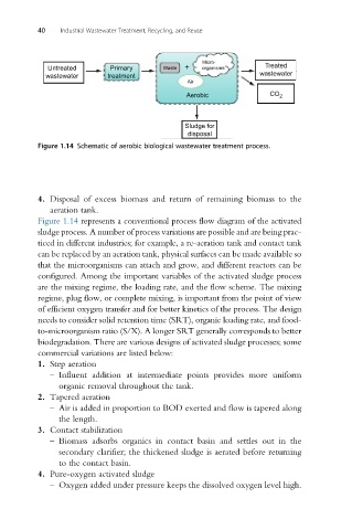
Figure 1.14 Schematic of aerobic biological wastewater treatment process.
4. Disposal of excess biomass and return of remaining biomass to the
aeration tank.
Figure 1.14 represents a conventional process flow diagram of the activated
sludge process. A number of process variations are possible and are being prac-
ticed in different industries; for example, a re-aeration tank and contact tank
can be replaced by an aeration tank, physical surfaces can be made available so
that the microorganisms can attach and grow, and different reactors can be
configured. Among the important variables of the activated sludge process
are the mixing regime, the loading rate, and the flow scheme. The mixing
regime, plug flow, or complete mixing, is important from the point of view
of efficient oxygen transfer and for better kinetics of the process. The design
needs to consider solid retention time (SRT), organic loading rate, and food-
to-microorganism ratio (S/X). A longer SRT generally corresponds to better
biodegradation. There are various designs of activated sludge processes; some
commercial variations are listed below:
1. Step aeration
– Influent addition at intermediate points provides more uniform
organic removal throughout the tank.
2. Tapered aeration
– Air is added in proportion to BOD exerted and flow is tapered along
the length.
3. Contact stabilization
– Biomass adsorbs organics in contact basin and settles out in the
secondary clarifier; the thickened sludge is aerated before returning
to the contact basin.
4. Pure-oxygen activated sludge
– Oxygen added under pressure keeps the dissolved oxygen level high.