
Page 183 - Innovations in Intelligent Machines
P. 183
State Estimation for Micro Air Vehicles 175
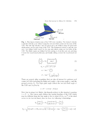
Fig. 1. This figures depicts some of the UAV state variables. The forward velocity
u and the roll rate p are defined along the roll axis which points out the nose of the
UAV. The side slip velocity v and the pitch rate q are defined along the pitch axis
which points out the right wing of the UAV. The downward velocity w and the yaw
rate r are defined with respect to the yaw axis which points out the belly of the
UAV. The Euler angles are defined by first yawing ψ about the yaw axis, pitching
θ about the transformed pitch axis, and finally rolling φ about the transformed roll
axis
⎛ ⎞ ⎛ ⎞
u cos α cos β
sin β . (1)
= V a
⎝ v ⎠ ⎝ ⎠
w sin α cos β
2
2
V a = u + v + w 2
w
α = tan −1 (2)
u
v
! "
−1
β = tan √ .
2
u + w 2
There are several other quantities that are also of interest for guidance and
control of UAVs including the flight path angle γ, the course angle χ, and the
ground velocity V g . The flight path angle defines the inertial climb angle of
the UAV and is given by
γ = θ − α cos φ − β sin φ.
Note that in wings level flight, this formula reduces to the standard equation
γ = θ − α. The course angle defines the inertial heading of the UAV which
T
may be different than the yaw angle ψ due to wind. If (w n ,w e ) is the wind
vector in the inertial frame, then we have the following relationships
! " ! " ! "
cos χ cos ψ cos γ w n
V g = V a +
sin χ sin ψ cos γ w e
#
! ! ""
−1 w e
2
2
2
2
2
V g = V cos γ +2V a cos γ w + w cos ψ − tan + w + w 2 e
n
e
n
a
w n