
Page 260 - Inorganic Mass Spectrometry - Fundamentals and Applications
P. 260
246 Delmore
portion of the filament facing the lens is shortened by about a factor of 4, with a
voltage drop of 0.5 V or less across the face, and the sample concen~ated close to
for
the lens on the face of the filament. This design has been useful a variety of ex-
periments in which the approximate 0.5” spread across the ion ernitter does not
cause complications.
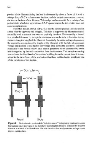
The other design, shown in Fig. 6.2, has the sample pressed into one end of
a tube with the opposite end plugged. This tube is supported by filament material
normally used in thermal ion sources, typically rhenium. The assembly is heated
as a standard filament is, except the resistance across the tube is less than the re-
sistance along the length of the filament. Essentially the entire voltage drop across
the assembly occurs along the length of the filament, with the tube at a constant
voltage that is close to one half of the voltage drop across the assembly. Since the
resistance of the tube is so low, little heat is generated by the current flow, so the
heat is supplied by thermal conduction from the filaments. This sample mounting
also reduces the likelihood of the emitter’s falling from the mount since it is con-
tained in the tube. Most of the work described later in this chapter employed one
of six variations of this design.
S
nt Sid
Illustration of a version of the “tube ion source.”Voltage is primarily across
drop
the fil~ent since the walls of the tube have much higher electrical conductivity than the
wall thickness. The tube therefore has nearly constant voltage across
filament as a result of
the ion emitting face.