
Page 121 - Solutions Manual to accompany Electric Machinery Fundamentals
P. 121
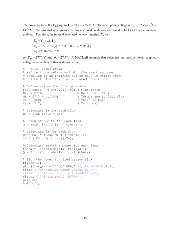
The power factor is 0.9 lagging, so I 90.2 25.8 A . The rated phase voltage is V = 3.2 kV / 3 =
A
1850 V. The saturated synchronous reactance at rated conditions was found to be 15.7 in the previous
problem. Therefore, the internal generated voltage (ignoring R A ) is
E V jX I
A S A
E 1850 j 0 15.7 90.2 A 25.8
A
E 2776 27.3 V
A
so E 2776 V and r 27.3 . A MATLAB program that calculates the reactive power supplied
Ar
voltage as a function of flux is shown below:
% M-file: prob4_26c.m
% M-file to calculate and plot the reactive power
% supplied to an infinite bus as flux is varied from
% 80% to 100% of the flux at rated conditions.
% Define values for this generator
flux_ratio = 0.80:0.01:1.00; % Flux ratio
Ear = 2776; % Ea at full flux
dr = 27.3 * pi/180; % Torque ang at full flux
Vp = 1850; % Phase voltage
Xs = 15.7; % Xs (ohms)
% Calculate Ea for each flux
Ea = flux_ratio * Ear;
% Calculate delta for each flux
d = asin( Ear ./ Ea .* sin(dr));
% Calculate Ia for each flux
Ea = Ea .* ( cos(d) + j.*sin(d) );
Ia = ( Ea - Vp ) ./ (j*Xs);
% Calculate reactive power for each flux
theta = -atan2(imag(Ia),real(Ia));
Q = 3 .* Vp .* abs(Ia) .* sin(theta);
% Plot the power supplied versus flux
figure(1);
plot(flux_ratio*100,Q/1000,'b-','LineWidth',2.0);
title ('\bfReactive power versus flux');
xlabel ('\bfFlux (% of full-load flux)');
ylabel ('\bf\itQ\rm\bf (kVAR)');
grid on;
hold off;
115