
Page 130 - Solutions Manual to accompany Electric Machinery Fundamentals
P. 130
(c) This motor has 6 poles and an electrical frequency of 60 Hz, so its rotation speed is n = 1200
m
r/min. The induced torque is
P 298.4 kW
OUT 3166 N m
ind
m 900 r/min 1 min 2 rad
60 s 1 r
The maximum possible induced torque for the motor at this field setting is the maximum possible power
divided by
m
3VE 3 480 V 406 V
ind,max A 10,340 N m
m X S 900 r/min 1 min 2 rad 0.6
60 s 1 r
The current operating torque is about 1/3 of the maximum possible torque.
(d) If the magnitude of the internal generated voltage E A is increased by 30%, the new torque angle
can be found from the fact that E A sin P constant .
E A 2 1.30 E A 1 1.30 406 V 487.2 V
E 1 406 V
sin 1 A 1 sin 1 sin sin 17.8 14.8
2
E A 2 487.2 V
The new armature current is
V E 480 0 V 487.2 14.8 V
I A 2 208 4.1 A
A
2
jX S j 0.6
The magnitude of the armature current is 208 A, and the power factor is cos (-24.1) = 0.913 lagging.
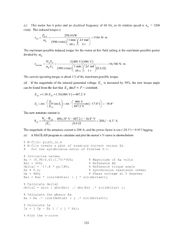
(e) A MATLAB program to calculate and plot the motor’s V-curve is shown below:
% M-file: prob5_1e.m
% M-file create a plot of armature current versus Ea
% for the synchronous motor of Problem 5-1.
% Initialize values
Ea = (0.90:0.01:1.70)*406; % Magnitude of Ea volts
Ear = 406; % Reference Ea
deltar = -17.8 * pi/180; % Reference torque angle
Xs = 0.6; % Synchronous reactance (ohms)
Vp = 480; % Phase voltage at 0 degrees
Ear = Ear * (cos(deltar) + j * sin(deltar));
% Calculate delta2
delta2 = asin ( abs(Ear) ./ abs(Ea) .* sin(deltar) );
% Calculate the phasor Ea
Ea = Ea .* (cos(delta2) + j .* sin(delta2));
% Calculate Ia
Ia = ( Vp - Ea ) / ( j * Xs);
% Plot the v-curve
124