
Page 153 - Solutions Manual to accompany Electric Machinery Fundamentals
P. 153
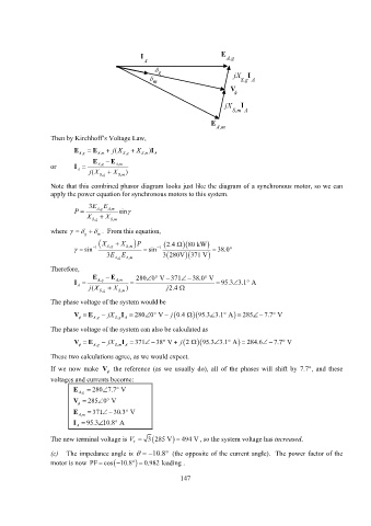
I E A,g
A
g
m jX I
S,g A
V
jX I
S,m A
E
A,m
Then by Kirchhoff’s Voltage Law,
E E ( jX X )I
, Ag , A m , S g , S m A
E E
or I , Ag , A m
A
( jX X )
, Sg , S m
Note that this combined phasor diagram looks just like the diagram of a synchronous motor, so we can
apply the power equation for synchronous motors to this system.
3EE
P , Ag , A m sin
X , Sg X , S m
where . From this equation,
g m
X X P 2.4 80 kW
sin 1 , Sg , S m sin 1 38.0
3E , Ag E , A m 3 280V 371 V
Therefore,
E E 280 0 V 371 38.0 V
,
I Ag , A m 95.3 3.1 A
A
( jX , Sg X , S m ) j 2.4
The phase voltage of the system would be
V E jX I 280 0 V j 0.4 95.3 3.1 A 285 7.7 V
, Ag , S g A
The phase voltage of the system can also be calculated as
V E jX I 371 38 V j 2 95.3 3.1 A 284.6 7.7 V
, Ag , S m A
These two calculations agree, as we would expect.
If we now make V the reference (as we usually do), all of the phases will shift by 7.7, and these
voltages and currents become:
E 280 7.7 V
, Ag
V 285 0 V
E 371 30.3 V
, Am
I 95.3 10.8 A
A
The new terminal voltage is V T 3 285 V 494 V , so the system voltage has increased.
(c) The impedance angle is 10.8 (the opposite of the current angle). The power factor of the
motor is now PF cos 10.8 0.982 lead ing .
147