Page 296 - Solutions Manual to accompany Electric Machinery Fundamentals
P. 296

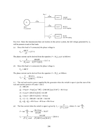
SOLUTION  Since the transmission lines are lossless in this power system, the full voltage generated by  G
                                                                                                              1
                 will be present at each of the loads.
                 (a)  Since this load is Y-connected, the phase voltage is

                              480 V
                         V           277 V
                           1 
                                 3
                 The phase current can be derived from the equation  P   3V I  cos  as follows:
                                                                     
                                 P        100 kW
                         I    1  3 cos      3 277 V 0.9     133.7 A
                                                
                              V
                                
                 (b)  Since this load is -connected, the phase voltage is
                         V   480 V
                          
                           2
                 The phase current can be derived from the equation  S   3V I  as follows:
                                                                      
                               S    80 kVA
                         I  2              55.56 A
                                     3V   3 480 V
                 (c)  The real and reactive power supplied by the generator when the switch is open is just the sum of the
                 real and reactive powers of Loads 1 and 2.
                         P  100 kW
                          1
                                                             
                         Q   1  P tan  P tan     1   cos PF   100 kW tan25.84     48.4 kvar
                         P   2  S cos   80 kVA 0.8      64 kW

                         Q   2  S sin   80 kVA 0.6     48 kvar
                                             
                                                     
                         P   G  P   1  P   2  100 kW 64 kW 164 kW
                         Q   G  Q   1  Q   2  48.4 kvar 48 kvar   96.4 kvar
                                                
                                                                              P                     Q
                 (d)  The line current when the switch is open is given by  I      , where    tan  1  G  .
                                                                      L
                                                                           3 V L cos               P G
                            tan   1 Q G    tan   1  96.4 kvar    30.45
                                 P G        164 kW

                                  P              164 kW
                         I                                     228.8 A
                          L
                               3 V L  cos         3 480 V cos   30.45


                                                           290
   291   292   293   294   295   296   297   298   299   300   301