
Page 295 - Solutions Manual to accompany Electric Machinery Fundamentals
P. 295
Therefore, the line voltage at the loads is V 3 V 439 V .
L
(b) The voltage drop in the transmission lines is
line V ,gen V ,load V 277 0 V 253.2 7.3 41.3 52 V
(c) The real and reactive power of each load is
V 2 253.2 V 2
P 1 3 Z cos 3 2.5 cos 36.87 61.6 kW
V 2 253.2 V 2
Q 1 3 Z sin 3 2.5 sin 36.87 46.2 kvar
V 2 253.2 V 2
P 3 cos 3 cos 20 108.4 kW
2
Z 1.67
V 2 253.2 V 2
Q 3 sin 3 sin 20 39.5 kvar
2
Z 1.67
(d) The line current is
41.3 52 V
V
I line line 225 8.6 A
Z line 0.09 j 0.16
Therefore, the loses in the transmission line are
P line 3I line 2 line 3 225 A 2 0.09 13.7 kW
R
Q line 3I line 2 line 3 X 225 A 2 0.16 24.3 kvar
(e) The real and reactive power supplied by the generator is
P gen P line P 1 P 2 13.7 kW 61.6 kW 108.4 kW 183.7 kW
Q gen Q line Q 1 Q 2 24.3 kvar 46.2 kvar 39.5 kvar 31 kvar
The power factor of the generator is
Q 31 kvar
PF cos tan -1 gen cos tan 1 0.986 lagging
P gen 183.7 kW
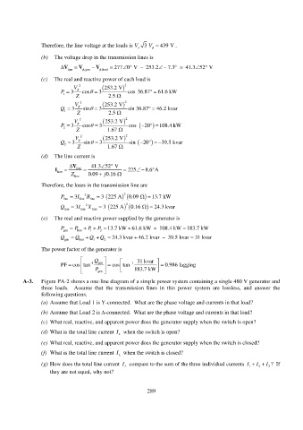
A-3. Figure PA-2 shows a one-line diagram of a simple power system containing a single 480 V generator and
three loads. Assume that the transmission lines in this power system are lossless, and answer the
following questions.
(a) Assume that Load 1 is Y-connected. What are the phase voltage and currents in that load?
(b) Assume that Load 2 is -connected. What are the phase voltage and currents in that load?
(c) What real, reactive, and apparent power does the generator supply when the switch is open?
(d) What is the total line current I L when the switch is open?
(e) What real, reactive, and apparent power does the generator supply when the switch is closed?
(f) What is the total line current I L when the switch is closed?
(g) How does the total line current I L compare to the sum of the three individual currents I I I ? If
2
3
1
they are not equal, why not?
289