
Page 331 - Solutions Manual to accompany Electric Machinery Fundamentals
P. 331
The current through the SCR consists of the current through resistor R plus the current through the
capacitor. The current through resistor R is 120 V / 20 k = 6 mA, and the holding current of the SCR is
8 mA, so the SCR will turn off when the current through the capacitor drops to 2 mA. This occurs at time
2 mA 250
t 0.0375 ln 0.206 s
120 V
(b) The SCR can be turned on again once the capacitor has discharged. The capacitor discharges
through resistor R. It can be considered to be completely discharged after three time constants. Since =
RC = (20 k)(150 F) = 3 s, the SCR will be ready to fire again after 9 s.
(c) In this circuit, the ON time of the SCR is much shorter than the reset time for the SCR, so power can
flow to the load only a very small fraction of the time. (This effect would be less exaggerated if the ratio
of R to R LOAD were smaller.)
(d) This problem can be eliminated by using one of the more complex series commutation circuits
described in Section 3-5. These more complex circuits provide special paths to quickly discharge the
capacitor so that the circuit can be fired again soon.
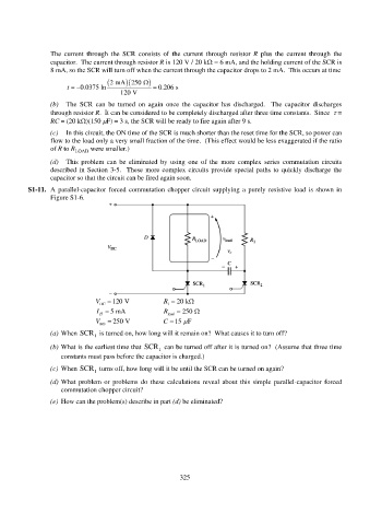
S1-11. A parallel-capacitor forced commutation chopper circuit supplying a purely resistive load is shown in
Figure S1-6.
V 120 V R 20 k
DC 1
I 5 mA R 250
H load
V 250 V C 15 F
BO
(a) When SCR is turned on, how long will it remain on? What causes it to turn off?
1
(b) What is the earliest time that SCR can be turned off after it is turned on? (Assume that three time
1
constants must pass before the capacitor is charged.)
(c) When SCR turns off, how long will it be until the SCR can be turned on again?
1
(d) What problem or problems do these calculations reveal about this simple parallel-capacitor forced
commutation chopper circuit?
(e) How can the problem(s) describe in part (d) be eliminated?
325