
Page 334 - Solutions Manual to accompany Electric Machinery Fundamentals
P. 334
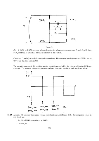
Figure (b)
(3) If SCR and SCR are now triggered again, the voltages across capacitors C and C will force
4
1
1
2
SCR and SCR to turn OFF. The cycle continues in this fashion.
3
2
Capacitors C and C are called commutating capacitors. Their purpose is to force one set of SCRs to turn
2
1
OFF when the other set turns ON.
The output frequency of this rectifier-inverter circuit is controlled by the rates at which the SCRs are
triggered. The resulting voltage and current waveforms (assuming a resistive load) are shown below.
S1-13. A simple full-wave ac phase angle voltage controller is shown in Figure S1-8. The component values in
this circuit are:
R = 20 to 300 k, currently set to 80 k
C = 0.15 F
328