
Page 339 - Solutions Manual to accompany Electric Machinery Fundamentals
P. 339
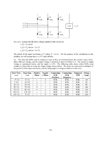
SOLUTION Assume that the three voltages applied to this circuit are:
V
vt M sin t
A
V
vt M sin t 2 / 3
B
V
vt M sin t 2 / 3
C
The period of the input waveforms is T, where T 2 / . For the purpose of the calculations in this
problem, we will assume that is 377 rad/s (60 Hz).
(a) The when the SCRs start to conduct as soon as they are forward biased, this circuit is just a three-
phase full-wave bridge, and the output voltage is identical to that in Problem 3-2. The sketch of output
voltage is reproduced below, and the ripple is 4.2%. The following table shows which SCRs must
conduct in what order to create the output voltage shown below. The times are expressed as multiples of
the period T of the input waveforms, and the firing angle is in degrees relative to time zero.
Start Time Stop Time Positive Negativ Conducting Conducting Triggered Firing
( t) ( t) Phase e Phase SCR SCR SCR Angle
(Positive) (Negative)
T / 12 T / 12 c b SCR 3 SCR 5 SCR 5 -30
T / 12 3T / 12 a b SCR 1 SCR 5 SCR 1 30
3T / 12 5T / 12 a c SCR 1 SCR 6 SCR 6 90
5T / 12 7T / 12 b c SCR 2 SCR 6 SCR 2 150
7T / 12 9T / 12 b a SCR 2 SCR 4 SCR 4 210
9T / 12 11T / 12 c a SCR 3 SCR 4 SCR 3 270
11T / 12 T / 12 c b SCR 3 SCR 5 SCR 5 330
333