
Page 333 - Solutions Manual to accompany Electric Machinery Fundamentals
P. 333
SOLUTION The last element in the filter of this rectifier circuit is an inductor, which keeps the current flow
out of the rectifier almost constant. Therefore, this circuit is a current source inverter. The rectifier and
filter together produce an approximately constant dc voltage and current across the two SCRs and diodes
at the right of the figure. The applied voltage is positive at the top of the figure with respect to the bottom
of the figure. To understand the behavior of the inverter portion of this circuit, we will step through its
operation.
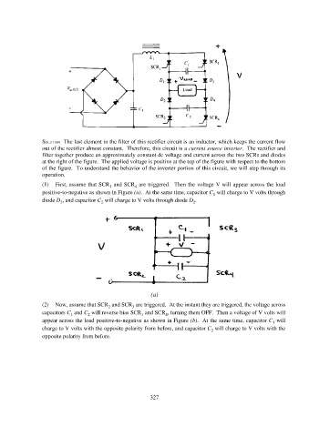
(1) First, assume that SCR and SCR are triggered. Then the voltage V will appear across the load
4
1
positive-to-negative as shown in Figure (a). At the same time, capacitor C will charge to V volts through
1
diode D , and capacitor C will charge to V volts through diode D .
2
2
3
(a)
(2) Now, assume that SCR and SCR are triggered. At the instant they are triggered, the voltage across
2
3
capacitors C and C will reverse bias SCR and SCR , turning them OFF. Then a voltage of V volts will
4
2
1
1
appear across the load positive-to-negative as shown in Figure (b). At the same time, capacitor C will
1
charge to V volts with the opposite polarity from before, and capacitor C will charge to V volts with the
2
opposite polarity from before.
327