
Page 82 - Solutions Manual to accompany Electric Machinery Fundamentals
P. 82
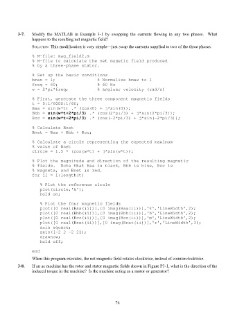
3-7.   Modify the MATLAB in Example 3-1 by swapping the currents flowing in any two phases.  What
                 happens to the resulting net magnetic field?
                 SOLUTION  This modification is very simple—just swap the currents supplied to two of the three phases.

                 % M-file: mag_field2.m
                 % M-file to calculate the net magetic field produced
                 % by a three-phase stator.

                 % Set up the basic conditions
                 bmax = 1;                % Normalize bmax to 1
                 freq = 60;               % 60 Hz
                 w = 2*pi*freq;           % angluar velocity (rad/s)

                 % First, generate the three component magnetic fields
                 t = 0:1/6000:1/60;
                 Baa = sin(w*t) .* (cos(0) + j*sin(0));
                 Bbb = sin(w*t+2*pi/3) .* (cos(2*pi/3) + j*sin(2*pi/3));
                 Bcc = sin(w*t-2*pi/3) .* (cos(-2*pi/3) + j*sin(-2*pi/3));

                 % Calculate Bnet
                 Bnet = Baa + Bbb + Bcc;

                 % Calculate a circle representing the expected maximum
                 % value of Bnet
                 circle = 1.5 * (cos(w*t) + j*sin(w*t));

                 % Plot the magnitude and direction of the resulting magnetic
                 % fields.  Note that Baa is black, Bbb is blue, Bcc is
                 % magneta, and Bnet is red.
                 for ii = 1:length(t)

                    % Plot the reference circle
                    plot(circle,'k');
                    hold on;

                    % Plot the four magnetic fields
                    plot([0 real(Baa(ii))],[0 imag(Baa(ii))],'k','LineWidth',2);
                    plot([0 real(Bbb(ii))],[0 imag(Bbb(ii))],'b','LineWidth',2);
                    plot([0 real(Bcc(ii))],[0 imag(Bcc(ii))],'m','LineWidth',2);
                    plot([0 real(Bnet(ii))],[0 imag(Bnet(ii))],'r','LineWidth',3);
                    axis square;
                    axis([-2 2 -2 2]);
                    drawnow;
                    hold off;

                 end
                 When this program executes, the net magnetic field rotates clockwise, instead of counterclockwise.
          3-8.   If an ac machine has the rotor and stator magnetic fields shown in Figure P3-1, what is the direction of the
                 induced torque in the machine?  Is the machine acting as a motor or generator?


                                                           76