
Page 92 - Solutions Manual to accompany Electric Machinery Fundamentals
P. 92
The magnitude of the phase current flowing in this generator is
E 9526 V 9526 V
I A 1004 A
A
R A jX S Z 0.2 j 2.5 8 25 9.49
Therefore, the magnitude of the phase voltage is
V I Z A 1004 A 8 8032 V
and the terminal voltage is
V T 3 V 3 8032 V 13,910 V
(b) Armature current is I A 1004 25 A , and the phase voltage is V 8032 0 V . Therefore, the
internal generated voltage is
E V R I jX I
A A A S A
E 8032 0 0.20 1004 25 A j 2.5 1004 25 A
A
E 9530 13.3 V
A
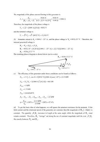
The resulting phasor diagram is shown below (not to scale):
E A 9530 13.3 V
I A R A jX I
SA
V 8032 0 V
I 1004 25 A
A
(c) The efficiency of the generator under these conditions can be found as follows:
P OUT 3 V I A cos 3 8032 V 1004 A cos 25 21.9 MW
P CU 3I A 2 A R 3 1004 A 2 0.2 605 kW
P F&W 1 MW
P core 1.5 MW
P stray (assumed 0)
P IN P OUT P CU P F&W P core P stray 25 MW
P 21.9 MW
OUT 100% 100% 87.6%
P IN 25 MW
(d) To get the basic idea of what happens, we will ignore the armature resistance for the moment. If the
field current and the rotational speed of the generator are constant, then the magnitude of E A K is
constant. The quantity jX I increases in length at the same angle, while the magnitude of E must
A
SA
remain constant. Therefore, E A “swings” out along the arc of constant magnitude until the new jX I
S S
fits exactly between V and E A .
86