
Page 18 - Instrumentation Reference Book 3E
P. 18
easurement of flow
G. FQWLES and W. H. BOYES
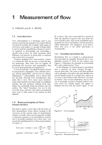
1.1 Introduction If, as above, flow rate is recorded for a period of
time, the quantity is equal to the area under the
Flow measurement is a technique used in any curve (shaded area). This can be established auto-
process requiring the transport of a material from matically by many instruments, and the process is
one point to another (for example, bulk supply of called integration. The integrator of an instru-
oil from a road tanker to a garage holding tank). ment may carry it out either electrically or
It can be used for quantifying a charge for mater- mechanically.
ial supplied or maintaining and controlling a
specific rate of flow. In many processes, plant 1.2.1 Streamlined and turbulent flow
efficiency will depend on being able to measure
and control flow accurately. Streamlined flow in a liquid is a phenomenon
Properly designed flow measurement systems best described by example. Reynolds did a con-
are compatible with the process or material they siderable amount of work on this subject, and
are measuring. They must also be capable of Figure 1.2 illustrates the principle of streamlined
producing the accuracy and repeatability that flow (also called laminar flow).
are most appropriate for the application. A thin filament of colored liquid is introduced
It is often said that “The ideal flowmeter should into a quantity of water flowing through a
be non-intrusive, inexpensive, have absolute accur- smooth glass tube. The paths of all fluid particles
acy, infinite repeatability, and run forever without will be parallel to the tube walls, and therefore the
maintenance.” Unfortunately, such a device does colored liquid travels in a straight line, almost as
not yet exist, although some manufacturers may if it were a tube within a tube. However, this state
claim that it does. Over recent years, however, is velocity- and viscosity-dependent, and as velo-
many improvements have been made to established city is increased, a point is reached (critical velo-
systems, and new products utilizing novel tech- city) when the colored liquid will appear to
niques are continually being introduced onto the disperse and mix with the carrier liquid. At this
market. The “ideal” flowmeter may not in fact
be so far away, and now more than ever potential
users must be fully aware of the systems at their 7
disposal.
1.2 Basic principles of flow
ni e a s u r e m e n t
We need to spend a short time with the basics of Timelh
flow measurement theory before looking at the Figure 1 .I Flow-time graph.
operation of the various types of measurement
systems available. Flow can be measured as either
a volumetric quantity or an instantaneous velocity
(this is normally translated into a flow rate). You
can see the interdependence of these measurements
in Figure 1.1.
(m3)
quantity = flow rate x time = ~. s = m3
(4 Figure 1.2 Reynolds’s experiment.