
Page 20 - Instrumentation Reference Book 3E
P. 20
Basic principles of flow measurement 5
V 1.2.3 Bernoulli’s theorem
4
All fluid flow formulas in a closed pipe are based
F on Bernoulli’s theorem. This states that in a
steady flow, without friction, the sum of potential
energy, kinetic energy, and pressure energy is a
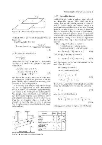
constant along any streamline. If we have a closed
pipe or channel (Figure 1.4) in which there are
Figure 1.3 Determination of dynamic viscosity two sections due to the placement of a restriction,
orifice, or hydraulic gradient, there is a pressure
or head loss in the transition from the first section
the fluid. This is illustrated diagrammatically in to the second. If 1 kg of fluid enters the pipe at the
Figure 1.3. first section, then 1 kg of fluid must leave at the
Thus for parallel flow lines second.
The energy of the fluid at section 1
force (F)
dynamic viscosity p = = potential energy + kinetic energy
area (A) x velocity (v) + pressure energy + internal energy
= 1 .z1 .g+;. 1. v;+p1 .Vl+Il (1.6)
or, if a velocity gradient exists,
The energy of the fluid at section 2
F
p = m = 1 .z,.g+$. 1. v;+~? .v2+r2 (1.7)
“Kinematic viscosity” is the ratio of the dynamic and since energy cannot leave the channel nor be
viscosity of a fluid to its density at the same created or destroyed,
temperature.
total energy at section 1
kinematic viscosity at T “C
=total energy at section 2
- dynamic viscosity at T “C
- (1.5)
density at T “C
For liquids the viscosity decreases with increase
of temperature at constant pressure; while for
gases viscosity will increase with increasing tem-
perature, at a constant pressure. Now, if the temperature of the fluid remains the
It is viscosity that is responsible for the damp- same the internal energy remains the same and
ing out or suppression of flow disturbances
caused by bends and valves in a pipe; the energy rl = I, (1.9)
that existed in the swirling liquid is changed into
heat energy. This is the reason manufacturers of and equation (1.8) reduces to
flow instruments require stated distances ahead
and behind the installation point of a flowmeter.
What they are trying to achieve is to allow fluid
viscosity to have the time to work to suppress (1.10)
flow disturbances and permit accurate and repea-
table readings. This equation applies to liquids and ideal gases.
section I ytion 1 Units I
Section 1 Section 2
At
At
Parameter
1
Area
Velocity
Pressure
Density
Specific volume of 1 Kq
Height of center of
gravity above
reference plane
Iz‘ Reference plane I I per Kg
Internal enerav
Figure 1.4 Hydraulic conditionsfor pipe flow.