
Page 25 - Instrumentation Reference Book 3E
P. 25
10 Measurement of flow
Radius between To sum up the venturi tube:
zero ond I.80 Exit Advantages
i’
0.50 0.50
1 diometw 1. Simple in operation
05dJg
2. Low head loss
3. Tolerance of high solids content
4. Long-term reliability
5. No moving parts
Disadvantages
1. Expensive
2. Square root pressure-velocity relationship
Radius between zero and 55d
Figurel.6 Venturi tube. Courtesy, British Standards 3. Poor turn-down ratio
4. Critical installation requirements
Institution.
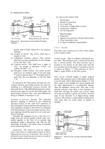
1.3.1.3 Nozzles
greater than 0.7420, where D is the entrance The other most common use of the venturi effect
diameter. is the venturi nozzle.
Length of throat. The throat shall have a
length of 1.0d.
Cylindrical entrance section. This section Venturi nozzle This is in effect a shortened ven-
shall have an internal diameter 0 and a length turi tube. The entrance cone is much shorter and
of not less than 1.0d. has a curved profile. The inlet pressure tap is
Conical section. This shall have a taper of located at the mouth of the inlet cone and the
lo$’,. Its length is therefore 2.70(0 - d) low-pressure tap in the plane of minimum section
within f0.24(D - d). as shown in Figure 1.7. This reduction in size is
Divergent outlet section. The outlet section taken a stage further in the flow nozzle.
shall have an inclined angle of not less than
5O and not greater than 15’. Its length shall be
such that the exit diameter is not less than Flow nozzle Overall length is again reduced
1 Sd. greatly. The entrance cone is bell-shaped and there
is no exit cone. This is illustrated in Figure 1.8. The
In operation the fluid passes through the con- flow nozzle is not suitable for viscous liquids but
vergent entrance, increasing velocity as it does so, for other applications it is considerably cheaper
resulting in a differential pressure between the than the standard venturi tube. Also, due to the
inlet and throat. This differential pressure is mon- smooth entrance cone there is less resistance to
itored in the same way as for the orifice plate, the fluid flow through the nozzle and a lower value
relationship between flow rate and differential of m may be used for a given rate of flow. Its main
being as defined in equation (1.24). area of use therefore is in high-velocity mains
where it will produce a substantially smaller pres-
Location of pressure tappings The upstream sure drop than an orifice plate of similar m
pressure tapping is located in the cylindrical number.
entrance section of the tube 0.5D upstream of
the convergent section and the downstream pres-
sure tapping is located in the throat at a distance
0.50 downstream of the convergent section. Pres-
sure tappings should be sized so as to avoid acci-
dental blockage.
Generally the tappings are not in the form of a
single hole but several equally spaced holes con-
nected together in the form of an annular ring
sometimes called a piezometer ring. This has the
advantage of giving a true mean value of pressure
at the measuring section.
Application The venturi is used for applica-
tions where there is a high solids content or where 0.030 for d/0 F 0 67
high pressure recovery is desirable. The venturi is 0020 fordD-067
inherently a low head-loss device and can result in Figure 1.7 Venturi nozzle Courtesy, British Standards
an appreciable saving of energy. Institution.