
Page 26 - Instrumentation Reference Book 3E
P. 26
Fluid flow in closed pipes 11
Pressure holes Throat pressure connection
upstream preiure connection
Figure 1 .IO Dall insert. Courtesy, British Standards
Institution.
Figure 1.8 Flow nozzle. Courtesy, British Standards
Institution. above critical flow as if the device were a venturi
tube. In the ‘transition zone’ between sub- and
1.3.1.4 Dall tube super-critical flow, the design of the unit permits
a reasonably accurate measurement. This design
This is another variation of the venturi tube and won an R&D100 Award in 1993 as one of the 100
gives a higher differential pressure but a lower head most important engineering innovations of the
loss than the conventional venturi tube. Figure 1.9 year.
shows a cross-section of a typical Dall flow tube. It
consists of a short straight inlet section, a conver-
gent entrance section, a narrow throat annulus and Pressure loss AI1 the differential pressure
a short divergent recovery cone. The whole device devices discussed so far cause an irrecoverable
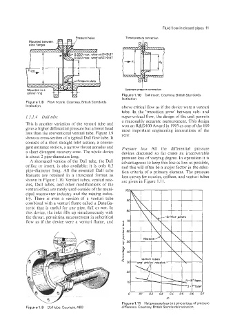
is about 2 pipe-diameters long. pressure loss of varying degree. In operation it is
A shortened version of the Dall tube, the Dall advantageous to keep this loss as low as possible,
orifice or insert, is also available; it is only 0.3 and this will often be a major factor in the selec-
pipe-diameter long. All the essential Dall tube tion criteria of a primary element. The pressure
features are retained in a truncated format as loss curves for nozzles, orifices, and venturi tubes
shown in Figure 1.10. Venturi tubes, venturi noz- are given in Figure 1.1 1.
zles, Dall tubes, and other modifications of the
venturi effect are rarely used outside of the muni-
cipal wastewater industry and the mining indus-
try. There is even a version of a venturi tube
combined with a ventu.ri flume called a DataGa-
torE that is useful for any pipe. full or not. In
this device, the inlet fills up simultaneously with
the throat, permitting measurement in subcritical
flow as if the device were a venturi flume, and
w rn
Figure 1 .I1 Net pressure loss as a percentage of pressure
Figurel.9 Dalltube. Courtesy,ABB difference. Courtesy, British Standards Institution.