
Page 24 - Instrumentation Reference Book 3E
P. 24
Fluid flow in closed pipes 9
1,3 Fluid flow in closed pipes
1.3.1 Differential-pressure devices
Differential pressure devices using a constriction
in the pipeline have been the most common tech-
nique for measuring fluid flow. Recently, other
devices have made substantial inroads in the basic
Mmrnum
measurement of fluids. Differential pressure is twice dro of
still a widely used technique, with even some
new devices that have been introduced in the
recent past. A recent estimate puts the use of Pressure
hole
differential pressure devices to measure flow in
the petrochemical industry at over 70 percent of
all flow devices. when d/D >O 67
As already shown in the derivation of Ber-
noulli's equation in the previous section, a con- @)
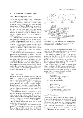
striction will cause an increase in fluid velocity in Figure 1.5 (a) Orifice platetypes. (b) Concentric orifice
the area of that constriction: which in turn will plate with D and 012 tappings mounted between flange
result in a corresponding pressure drop across the plates. Courtesy, British Standards Institution.
constriction. This differential pressure (d.p.) is a
function of the flow velocity and density of the
fluid and is shown to be a square root relation- Several design modifications can overcome these
ship; see equation (1.24). problems in the form of segmental or eccentric
A flowmeter in this category would normally orifice plates as shown in Figure lS(a).
comprise a primary element to develop a differen- The segmental orifice provides a method for
tial pressure and a secondary element to measure it. measuring the flow of liquids with solids in
The secolndary element is effectively a pressure suspension. It takes the form of a plate that
transducer, and operational techniques are dis- covers the upper cross-section of the pipe leav-
cussed in Chapter 9, so no further coverage will be ing the lower portion open for the passage of
given here. However there are various types of solids to prevent their build-up.
primary element and these deserve further consid- The eccentric orifice is used on installations
eration. The main types of interest are: orifice plate, where condensed liquids are present in gas-flow
venturi? nozzle, Dall, rotameter, gate meter, Gilflo measurement or where undissolved gases are pre-
element, iarget meter, and V-Cone. sent in the measurement of liquid flow. It is also
useful where pipeline drainage is required.
To sum up the orifice plate:
1.3.1.1 Orifice plate
Advantages
An orifice plate in its simplest form is a thin steel 1. Inherently simple in operation
plate with a circular orifice of known dimensions 2. No moving parts
located centrally in the plate. This is termed a con- 3. Long-term reliability
centric orifice plate; see Figure l.S(a). The plate 4. Inexpensive
would normally be clamped between adjacent Disadvantages
flange fittings in a pipeline, a vent hole and drain 1. Square root relationship
hole being provided to prevent solids building up 2. Poor turn-down ratio
arid gas pockets developing in the system; see 3. Critical installation requirements
Figure l.S(b). 4. High irrecoverable pressure loss
The differential pressure is measured by suita-
bly located pressure tappings on the pipeline on
either side of the orifice plate. These may be 1.3.1.2 Venturi tube
located in various positions depending on the appli-
cation (e.g., corner, D and 0/2, or flange tappings), The classical venturi tube is shown in Figure 1.6.
It comprises a cylindrical inlet section followed
and reference should be made to BS 1042 Part 1 by a convergent entrance into a cylindrical throat
1964 for correct application. Flow rate is deter- and a divergent outlet section. A complete speci-
mined from equation (1.24). fication may be found by reference to BS 1042
This type of orifice plate is inadequate to cope
with difficult conditions experienced in metering Part 1 1964 and relevant details are repeated here:
drty or viscous fluids and gives a poor disposal (a) Diameter of throat. The diameter d of the
rate of condensate in flowing steam and vapors. throat shall be not less than 0.2240 and not