
Page 28 - Instrumentation Reference Book 3E
P. 28
Fluid flow in closed pipes 13
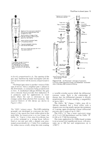
Maximum flow rate due to maximum
annular area is obtained with float
at large end of tube
Noting position of edge of float
'referred to capacity scale on glass
gives flow rate reading
Metering float suspended freely
in fluid being metered
Tapered transparent metering
-tube (borosilicate glass)
Minimum annular area and minimum
flow rate is obtained
Fluid passes through this annular
opening between periphery
of float head and I.D. of tapered
tube. Of course, flow rate varies
directly as area of annular opening (4
varies
is directly proportional to A2. The opening of the
gate may therefore be made rectangular and the
vertical movement will be directly proportional to Figure 1.12 (a) Rotameter-principle of operation.
flow. Courtesy, ABB Instrument Group. (b) Rotameter-exploded
The hinged gate meter is another version of this view. Courtesy, ABB Instrument Group.
type of device. Here a weighted gate is placed in
the flowstream, its deflection being proportional
to flow. A mechanical linkage between the gate
and a recorder head provides flow indication. It a variable annulus across which the differential
is primarily used for applications in water pressure varies. Such is the relationship of
mains where the user is interested in step change that the differential pressure is directly
changes rather than absolute flow accuracy. The proportional to flowrate enabling a rangeability
essential features of this device are shown in of up to 100: 1.
Figure l.l3(c). The Gilflo "B," Figure l.l4(b), sizes 40 to
300mm standard, has a fixed orifice with a
shaped cone moving axially against the resistance
The "Gilf7o"priinarj~ seizsoi, The Gilflo metering of a spring, again producing a linear differential
principle was developed to overcome the limit- pressure and a range of up to 100: 1.
ations of the square law fixed orifice plate in the The Gilflo "A" has a water equivalent range
mid-1960s. Its construction is in two forms: the of 0-5 to 0-350 literdminute and the Gilflo "B"
Gilflo .'A:' Figure l.l4(a), sizes 10 to 40 mm, has 0-100 to 0-17 500 liters/minute.
an orifice mounted to a strong linear bellows The main application for Gilflo-based systems
fixed at one end and with a shaped cone posi- is on saturated and superheated steam, with pres-
tioned concentrically in it. Under flow conditions sures up to 200 bar and temperatures up to
the orifice moves axially along the cone creating 1500 "C.