
Page 32 - Instrumentation Reference Book 3E
P. 32
Fluid flow in closed pipes 17
piston but by a movable disc mounted on a con-
centric sphere. The basic construction is shown in
Figure 1.18.
The liquid enters the left side of ;lie meter,
alternately above and below the disc. forcing it
to rock (nutate) in a circular path without rotat-
ing about its own axis. The disc is contained in a
spherical working chamber and is restricted
from rotating about its own axis by a radial
partition that extends vertically across the cham-
ber. The disc is slotted to fit over this partition.
The spindle protruding from the sphere traces
a circular path and is used to drive a geared
register.
This type of meter can be used for a wide
variety of liquids-disc and body materials being
Inlet chosen to suit.
Figure 1.17 Reciprocating-piston meter
drive the piston downwards, discharging the liquid Fluted-sp irai-ro tor type (r-otat ing- iinpclkei type)
from below the piston to the outlet pipe. The pro- The principle of this type of meter is shown in
cess repeats. Figure 1.19. The meter consists of two fluted rotors
As the piston reciprocates, a ratchet attached supported in sleeve-type bearings and mounted so
to the piston rod provides an actuating force for as to rotate rather like gears in a liquid-tight case.
an incremental counter, each count representing a The clearance between the rotors and measuring
pre-determined quantity of liquid. Newer devices chambers is kept tu a minimum. The shape of the
use magnetically coupled sensors-Hall-effect rotors is designed so that a uniform uninterrupted
or Wiegand-effect types being quite corninon; or rotation is produced by the liquid. The impellers in
optical enscoders to produce the count rate. turn rotate the index of a counter which shows the
total measured quantity.
This type of meter is used mainly for measuring
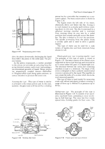
Nutating-disc type This type of meter is similar crude and refined petroleum products covering a
in principle to the rotary-piston type. In this case, range of flows up to 3000 m3/h at pressures up to
however, the gear train is driven not by a rotating 80 bar.
Sliding-vane type The principle of this type is
illustrated in Figure 1.20. It consists of an accur-
ately machined body containing a rotor revolv-
ing on ball bearings. The rotor has four evenly
spaced slots, forming guides for four vanes. The
Fluted
Fluted
Fluted
/
lnlel port Working chamber
Figure 1.18 Nutating-disc meter. Figure 1.1 9 Fluted-spiral-rotor type of meier.