
Page 34 - Instrumentation Reference Book 3E
P. 34
Fluid flow in closed pipes 19
through nozzles to impinge on the rotors of a
small turbine located in the bypass, the rotation
of the turbine being propo-tional to flow rate.
This type of device can give moderate accuracy
over a 5:l turn-down ratio and is suitable for
liquids, gases, and steam. Bypass meters have
been used with other shunt-meter devices, including
Coanda-effect oscillatory flow meters, rotameters,
ultrasonic meters, and positive displacement meters
and multijets.
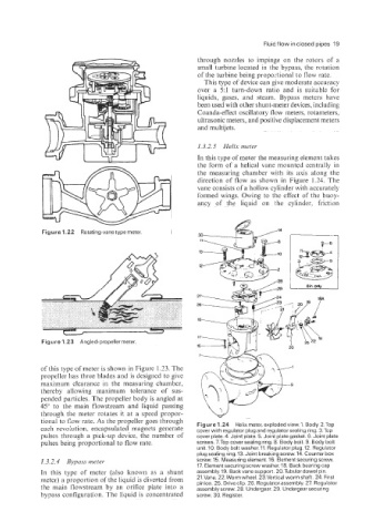
1.3.2.5 Helix meter
In this type of meter the measuring element takes
the form of a helical vane mounted centrally in
the measuring chamber with its axis along the
direction of flow as shown in Figure 1.24. The
vane consists of a hollow cylinder with accurately
formed wings. Owing to the effect of the buoy-
ancy of the liquid on the cylinder, friction
Figure 1.22 Rotating-vane type meter.
Figure 1.23 Angled-propeller meter.
of this type of meter is shown in Figure 1.23. The
propeller has three blades and is designed to give
maximum clearance in the measuring chamber,
thereby allowing maximum tolerance of sus-
pended particles. The propeller body is angled at
45" to the main flowstream and liquid passing
through the meter rotates it at a speed propor-
tional to flow rate. As the propeller goes through
Figure 1.24 Helix meter, exploded view. 1. Body. 2.Top
each revoiution, encapsulated magnets generate cover with regulator plug and regulator sealing ring. 3.Top
pulses through a pick-up device, the number of cover plate. 4. Joint plate. 5. Joint plate gasket. 6. Joint plate
pulses being proportional to flow rate. screws. 7.Top cover sealing ring. 8. Body bolt. 9. Body bolt
unit.10. Body bolt washer.11. Regulator plug. 12. Regulator
plug sealing ring. 13. Joint breaking screw. 14. Counter box
1.3.2.4 Bypass meter screw. 15. Measuring element. 16. Element securing screw.
17. Element securing screw washer. 18. Back bearing cap
In this type of meter (also known as a shunt assembly. 19. Back vane support. 20.Tubular dowel pin.
meter) a proportion of the liquid is diverted from 21.Vane. 22.Worm wheel. 23.Vertical worm shaft. 24. First
pinion. 25. Drive clip. 26. Regulator assembly. 27. Regulator
the main flowstream by an orifice plate into a assembly screw. 28. Undergear. 29. Undergear securing
bypass configuration. The liquid is concentrated screw. 30. Register.