
Page 39 - Instrumentation Reference Book 3E
P. 39
24 Measurement of flow
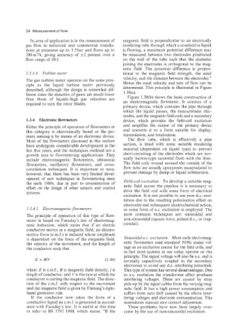
Its area of application is in the measurement of magnetic field is perpendicular to an electrically
gas flow in industrial and commercial installa- insulating tube through which a conductive liquid
tions at pressures up to 1.5 bar and flows up to is flowing, a maximum potential difference may
200m3/h, giving accuracy of *2 percent over a be measured between two electrodes positioned
flow range of 1O:l. on the wall of the tube such that the diameter
joining the electrodes is orthogonal to the mag-
netic field. The potential difference is propor-
1.3.3.4 Turbine meter tional to the magnetic field strength, the axial
The gas turbine meter operates on the same prin- velocity, and the distance between the electrodes.”
ciple as the liquid turbine meter previously Hence the axial velocity and rate of flow can be
described, although the design is somewhat dif- determined. This principle is illustrated in Figure
ferent since the densities of gases are much lower 1.30(a).
than those of liquids-high gas velocities are Figure 1.30(b) shows the basic construction of
required to turn the rotor blades. an electromagnetic flowmeter. It consists of a
primary device, which contains the pipe through
which the liquid passes, the measurement elec-
trodes, and the magnetic field coils and a secondary
1.3.4 Electronic flowmeters device, which provides the field-coil excitation
Either the principle of operation of flowmeters in and amplifies the output of the primary device
this category is electronically based or the pri- and converts it to a form suitable for display,
mary sensing is by means of an electronic device. transmission, and totalization.
Most of the flowmeters discussed in this section The flow tube, which is effectively a pipe
have undergone considerable development in the section, is lined with some suitable insulating
last five years, and the techniques outlined are a material (dependent on liquid type) to prevent
growth area in flowmetering applications. They short-circuiting of the electrodes which are nor-
include electromagnetic flowmeters, ultrasonic mally button-type mounted flush with the liner.
flowmeters, oscillatory flowmeters, and cross- The field coils wound around the outside of the
correlation techniques. It is important to note, flow tube are usually epoxyresin encapsulated to
however, that there has been very limited devel- prevent damage by damp or liquid submersion.
opment of new techniques in flowmetering since
the early 198Os, due in part to concentration of Field-coil excitation To develop a suitable mag-
effort on the design of other sensors and control netic field across the pipeline it is necessary to
systems. drive the field coil with some form of electrical
excitation. It is not possible to use pure d.c. exci-
tation due to the resulting polarization effect on
electrodes and subsequent electrochemical action,
1.3.4.1 Electvomagnetic flowmeters so some form of a.c. excitation is employed. The
The principle of operation of this type of flow- most common techniques are: sinusoidal and
meter is based on Faraday’s law of electromag- non-sinusoidal (square wave, pulsed d.c., or trap-
netic induction, which states that if an electric ezoidal).
conductor moves in a magnetic field, an electro-
motive force (e.m.f.) is induced whose amplitude
is dependent on the force of the magnetic field, Sinusoidal a. c. excitation Most early electromag-
the velocity of the movement, and the length of netic flowmeters used standard 50Hz mains vol-
the conductor such that tage as an excitation source for the field coils, and
in fact most systems in use today operate on this
principle. The signal voltage will also be a.c. and is
Ex BlV (1.44) normally capacitively coupled to the secondary
electronics to avoid any d.c. interfering potentials.
where E is e.m.f., B is magnetic field density, 1 is This type of system has several disadvantages. Due
length of conductor, and Vis the rate at which the to ax. excitation the transformer effect produces
conductor is cutting the magnetic field. The direc- interfering voltages. These are caused by stray
tion of the e.m.f. with respect to the movement pick-up by the signal cables from the varying msrg-
and the magnetic field is given by Fleming‘s right- netic field. It has a high power consumption and
hand generator rule. suffers from zero drift caused by the above inter-
If the conductor now takes the form of a fering voltages and electrode contamination. This
conductive liquid an e.m.f. is generated in accord- necessitates manual zero control adjustment.
ance with Faraday’s law. It is useful at this time These problems have now been largely over-
to refer to BS 5792 1980, which states: “If the come by the use of non-sinusoidal excitation.