
Page 40 - Instrumentation Reference Book 3E
P. 40
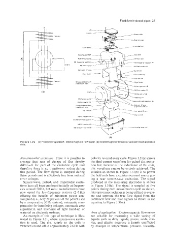
Fluid flow in closed pipes  25


                                                                 (b)
             Figure 4.30 (a) Principle of operation-electromagnetic  flowmeter. (b) Electromagnetic flowmeter detector head: exploded
             view.


             Non-sinusoidal  excitation  Here  it is possible to   polarity reversal every cycle. Figure 1.3 l(a) shows
             arrange  that  rate  of  change  of  flux  density   the ideal current waveform for pulsed d.c. excita-
             dBldt = 0  for  part  of  the  excitation  cycle  and   tion but, because of  the inductance of  the coils,
             therefore  there  is  no  transformer  action  during   this waveform  cannot  be  entirely achieved. The
             this  period.  The  flow  signal  is  sanipled  during   solution  as shown in Figure  1.31(b) is to power
             these periods and is effectively free from induced   the field coils from a constant-current source giv-
             error voltages.                          ing  a  near  square-wave  excitation.  The  signal
               Square-wave,  pulsed,  and  trapezoidal  excita-   produced  at  the  measuring  electrodes  is  shown
             tions have all been employed initially at frequen-   in  Figure  1,31(c). The  signai is  sampled  at  five
             cies around 50 Hz, but most manufacturers have   points during each measurement cycle as shown,
             now  opted  for  low-frequency  systems  (2-7  Hz)   microprocessor techniques being utilized to evalu-
             offering  the  benefits  of  minimum  power  con-   ate  and  separate  the  true  flow  signal  from the
             sumption (Le., only 20 per cent of the power used   combined flow and zero signals as shown in the
             by a comparative 50 Hz system), automatic com-   equation in Figure 1.31(c).
             pensatioii for interfering voltages, automatic zero
             adjustmeit,  and  tolerance  of  light  build-up  of
             material on electrode surfaces.          Area of  application  Electromagnetic flowmeters
               An exarr-ple of  this type  of  technique  is illus-   are  suitable  for  measuring  a  wide  variety  of
             trated  in Figure  1.31, where square-wave excita-   liquids  such as dirty  liquids,  pastes,  acids, slur-
             tion  is  used.  The  d.c.  supply  tQ the  coils  is   ries,  and  alkalis;  accuracy  is  largely  unaffected
             switched on and off at approximately 2.6 Hz with   by  changes  in  temperature,  pressure,  viscosity,