
Page 45 - Instrumentation Reference Book 3E
P. 45
Measurement of flow
allow transfer of oil between the two sides.
An electrode is placed close to each plate and
the oil used as a dielectric. The vortices alter-
nately deform the diaphragm plates causing a
capacitance change between the diaphragm
and electrode. The frequency of changes in
capacitance is equal to the shedding frequency.
Strain. Here the bluff body is designed such
that the alternating pressures associated with
vortex shedding are applied to a cantilevered
section to the rear of the body. The alternat-
ing vortices create a cyclic strain on the rear
of the body which is monitored by an internal
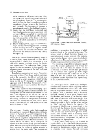
strain gauge. Figure 1.38 Cutawayview of theswirlmeter. Courtesy,
Shuttle ball (Figure 1.37(f)). The shuttle tech- ABB Instrument Group.
nique uses the alternating pressures caused by
vortex shedding to drive a magnetic shuttle
up and down the axis of a flow element. The oscillation or precession, the frequency of which
motion of the shuttle is detected by a mag- is proportional to the volumetric flow rate. The
netic pick-up. sensor, which is a bead thermistor heated by a
constant-current source, converts the instanta-
The output derived from the primary sensor is neous velocity changes into a proportional electri-
a low-frequency signal dependent on flow; this is cal pulse output. The number of pulses generated is
then applied to conditioning electronics to pro- directly proportional to the volumetric flow.
vide either analog or digital output for display The operating range of the swirlmeter depends
and transmission. The calibration factor (pulses upon the specific application, but typical for
per m3) for the vortex meter is determined by the liquids are 3.5 to 4.0 liters per minute for the
dimensions and geometry of the bluff body and 25mm size to 1700 to 13,000 liters per minute
will not change. for the 300mm size. Typical gas flow ranges
Installation parameters for vortex flowmeters are 3 to 35m3/h for the 25mm size to 300 to
are quite critical. Pipe flange gaskets upstream 9000m3/h for the 300min size. Accuracy of
and at the transmitter should not protrude into d~l per cent of rate is possible with repeatability
the flow, and to ensure a uniform velocity profile of 50.25 per cent of rate.
there should be 20 diameters of straight pipe
upstream and 5 diameters downstream. Flow-
straighteners can be used to reduce this require- The Coanda effect meters The Coanda effect pro-
ment if necessary. duces a fluidic oscillator whose frequency is linear
The vortex flowmeter has wide-ranging appli- with the volumetric flow rate of fluid. The Coanda
cations in both gas and liquid measurement pro- effect is a hydraulic feedback circuit. A chamber
viding the Reynolds number lies between 2 x lo3 is designed with a left-hand and a right-hand
and 1 x lo5 for gases and 4 x lo3 and 1.4 x lo5 for feedback channel. A jet of water flows through
liquids. The output of the meter is independent of the chamber, and because of the feedback chan-
the density, temperature, and pressure of the flow- nels, some of the water will impact the jet from
ing fluid and represents the flow rate to better the side. This causes a pressure differential
than *1 per cent of full scale giving turn-down between one side of the jet and the other, and the
ratios in excess of 20: 1. jet “flips” back and forth in the chamber. The
frequency of this flipping is proportional to the
flow through the chamber. Several means exist to
The swirlmeter Another meter that depends on measure this oscillation, including electromag-
the oscillatory nature of fluids is the swirlmeter netic sensors and piezo-resistive pressure trans-
shown in Figure 1.38. A swirl is imparted to the ducers. This coanda effect is extremely linear
body of flowing fluid by the curved inlet blades and accurate across at least a 300:l range. It is
which give a tangential component to the fluid reasonably viscosity independent, too, and can be
flow. Initially the axis of the fluid rotation is the made simply and inexpensively.
center line of the meter, but a change in the Typically, small fluidic meters can be made so
direction of the rotational axis (precession) takes inexpensively, in fact, that fluidic flowmeters are
place when the rotating liquid enters the enlarge- being promoted as a replacement for the inexpen-
ment, causing the region of highest velocity to sive positive displacement meters currently used
rotate about the meter axis. This produces an as domestic water meters. Several companies