
Page 46 - Instrumentation Reference Book 3E
P. 46
Fluid flow in closed pipes 31
have developed fluidic flow meters as extremely
inexpensive replacements for AGA-approved dia-
phragm-type gas meters for household metering.
Coanda effect meters are insensitive to tem-
perature change, too. A fluidic flowmeter is being
marketed as an inexpensive BTU (heat) meter for
district heating applications. Coanda effect
meters become more expensive as their physical
size increases. Above 50 mm diameter, they are
more expensive in general than positive-displace-
ment meters. Currently, the only designs avail-
able above 50mm are “bypass designs” that use
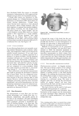
a small diameter coanda effect meter as a bypass Figure 1.39 Coanda Effect Fluidic Meter, courtesyof
around a flow restriction in a larger pipeline. Mycrosensor, Inc.
Meters up to 250 mm diameter have been
designed in this fashion. These meters exhibit
rangeability of over 100:1, with accuracies (when is beyond the scope of this book but the user
corrected electronically for linearity shift) of 0.5% should be aware of the problem and ensure where
of indicated flow rate. See Figure 1.39. possible that the flow is as near homogeneous as
possible (by pipe-sizing or meter-positioning) or
that the two phases are separately metered.
1.3.4.4 Cross-correlation
Methods of measurement can be categorized
In most flowing fluids there exist naturally occur- under two main headings: true mass-flow meas-
ring random fluctuations such as density, turbu- urement in which the measured parameter is
lence, and temperature which can be detected by directly related to mass flow rate, and inferential
suitably located transducers. If two such trans- mass-flow measurement in which volume flow
ducers are installed in a pipeline separated by a rate and fluid density are measured and combined
distance L as shown in Figure 1.40, the upstream to give mass flow rate. Since volume flow rate and
transducer will pick up a random fluctuation t density measurement are discussed elsewhere only
seconds before the downstream transducer and true mass-flow measurement will be dealt with here.
the distance between the transducers divided by
the transit time t will yield flow velocity. In prac- 1.3.5. I True nzass-Jon. measurement methods
tice the random fluctuations will not be stable
and are compared in a cross-correlator which Fluid-momentum method.7 (a) Angular momen-
has a peak response at transit time T,, and correl- tum. This type of device consists of two turbines
ation velocity V = UT, meters per second. on separate axial shafts in the meter body. The
This is effectively a non-intrusive measurement upstream turbine is rotated at constant speed and
and could in principle be developed to measure imparts a swirling motion to the fluid passing
flow of most fluids. Very few commercial cross- through it. On reaching the downstream turbine,
correlation systems are in use for flow measure- the swirling fluid attempts to impart motion onto
ment because of the slow response time of such it; however, this turbine is constrained from
systems. However, with the use of microprocessor rotating by a calibrated spring. The meter is
techniques processing speed has been increased designed such that on leaving the downstream
significantly, and several manufacturers are now turbine all angular velocity will have been
producing commercial systems for industrial use. removed from the fluid, and the torque produced
Techniques for effecting the cross-correlation on it is proportional to mass flow.
operation are discussed in Part 4. This type of device can be used for both gases
and liquids with accuracies of fl percent.
(b) GyroscopidCoriolis mass flowmeter. Mass
1.3.5 Mass flowmeters
flowmeters in this category use the measurement
The measurement of mass flow rate can have of torque developed when subjecting the fluid
certain advantages over volume flow rate, i.e., stream to a Coriolis acceleration,* as a measure
pressure, temperature, and specific gravity do of mass flow rate.
not have to be considered. The main interfering
parameter to be avoided is that of two-phase flow
where gadliquid, gaslsolid or liquidlsolid mix- *On a rotating surface there is an inertial force acting
tures are flowing together in the same pipe. The on a body at right angles to its direction of motion in
two phases may be travelling at different veloci- addition to the ordinary effects of motion of the body.
ties and even in different directions. This problem This force is known as a Coriolis force.