
Page 47 - Instrumentation Reference Book 3E
P. 47
32 Measurement of flow
-
Flow iVi
A B
TD T
Time delay
Figure 1.40 Cross-correlation meter.
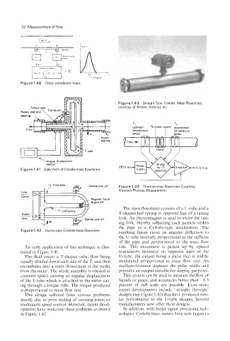
Figure 1.43 StraightTube Coriolis Mass Flowmeter,
courtesy of Krohne America Inc.
\Angular displacement
readout
Figure 1.41 Early form of Coriolis mass flowmeter.
I I
--Optical pick.off Figure 1.44 Thermal mass flowmeter. Courtesy,
- Emerson Process Measurement.
Inlet
Outlet
The mass flowmeter consists of a U-tube and a
T-shaped leaf spring as opposite legs of a tuning
Outlet
-
Inlet fork. An electromagnet is used to excite the tun-
ing fork, thereby subjecting each particle within
the pipe to a Coriolis-type acceleration. The
Figure 1.42 Gyroscopic/Coriolis mass flowmeter.
resulting forces cause an angular deflection in
the U-tube inversely proportional to the stiffness
of the pipe and proportional to the mass flow
An early application of this technique is illus- rate. This movement is picked up by optical
trated in Figure 1.41. transducers mounted on opposite sides of the
The fluid enters a T-shaped tube, flow being U-tube, the output being a pulse that is width-
equally divided down each side of the T, and then modulated proportional to mass flow rate. An
recombines into a main flowstream at the outlet oscillatorlcounter digitizes the pulse width and
from the meter. The whole assembly is rotated at provides an output suitable for display purposes.
constant speed, causing an angular displacement This system can be used to measure the flow of
of the T-tube which is attached to the meter cas- liquids or gases, and accuracies better than 3~0.5
ing through a torque tube. The torque produced percent of full scale are possible. Even more
is proportional to mass flow rate. recent developments include “straight through”
This design suffered from various problems designs (see Figure 1.43) that have produced simi-
mainly due to poor sealing of rotating joints or lar performance to the U-tube designs. Several
inadequate speed control. However, recent devel- manufacturers now offer these designs.
opments have overcome these problems as shown In addition, with better signal processing tech-
in Figure 1.42. nologies, Coriolis mass meters have now begun to